Wein Bridge Oscillator
It is a sinusoidal oscillator that uses a bridge circuit developed by Max Wein in 1891. It uses a bandpass filter (called Wein-bridge circuit) in a positive feedback loop to satisfy the Barkhausen criteria. The advantage of this oscillator is that it uses only one opamp to generate the sinusoidal signal.
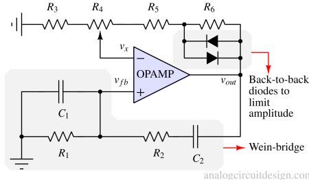
Working principle of Wein-bridge oscillator
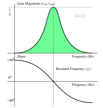
A low pass filter follows a high pass filter to form a bandpass filter. This bandpass filter's center frequency is the oscillation frequency. At this center frequency (ωo=1/RC), the gain (vfb/vout) is 1/3, as mentioned below :
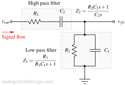
$$\cfrac{v_{fb}}{v_{out}}=\cfrac{Z_1}{Z_1+Z_2}$$
$$\implies{}\cfrac{v_{fb}}{v_{out}}=\cfrac{R_1C_1s}{s^2R_1R_2C_1C_2+s(R_1C_2+R_2C_2+R_1C_1)+1}$$
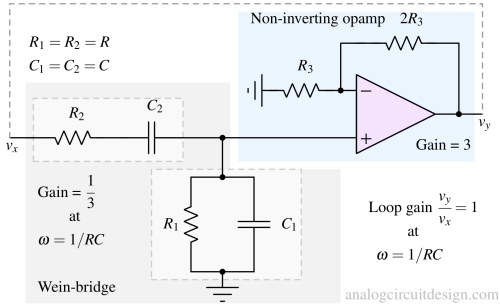
Usually, for simplicity, R1=R2=R, C1=C2=C. Therefore :
$$\implies{}\cfrac{v_{fb}}{v_{out}}=\cfrac{RCs}{s^2R^2C^2+3sRC+1}$$
Substituting s = jωo = j/RC in the above equation :
$$\cfrac{v_{fb}}{v_{out}}=\cfrac{1}{3}$$
To satisfy Barkhausen's criteria, we need to provide a gain of 3 so that the overall loop gain is 1, as shown in Fig 4.
Amplitude determination
We know from the article of Barhausen's criteria that if the loop gain > 1, the oscillation amplitude increase, and if the loop gain < 1, then the oscillation amplitude decrease.
To start the oscillations, the loop gain is kept higher than 1. This is to facilitate amplitude growth. When the amplitude reaches the desired value, the loop gain is kept equal to 1 using a nonlinear circuit. The gain of the nonlinear circuit is dependent on the amplitude it sees.
A non-inverting amplifier with a back-to-back diode is an amplitude-dependent gain circuit. That is exactly what is used in the complete Wein-bridge circuit.
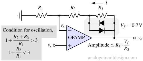
In the above figure, if,
$$|i\cdot{}R_3| < V_f$$
then the gain is,
$$G = 1+\cfrac{R_2+R_3}{R_1}$$
If,
$$|i\cdot{}R_3| > V_f$$
the diode is active, and it shorts R3. So, when the diode is active, the gain drops to,
$$G = 1+\cfrac{R_2}{R_1}$$