Thyristor (SCR)
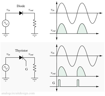
Thyristors or Silicon-controlled-rectifers (SCRs) are 3-terminal devices having PNPN junction profile. We can understand the basic operation of a thyristor by considering a half-wave rectifier circuit. In half wave rectifier circuit, diode conducts when the input is positive. We don't have the control to turn on/off the diode when the input voltage is positive (during forward bias). However, in a thyristor we can control the conduction phase when the input is positive. When input is negative, both diode and thyristor turns off.

Symbol and Terminals of Thyristor
The control terminal of the thyristor is called the gate (G) electrode. The other two terminals called the anode (A) and cathode (K) conduct the current through the thyristor. The anode and cathode terminals are connected in series with the load.

Symbol of thyristor looks like a diode. Only difference is the extra control terminal.
Construction of Thyristor
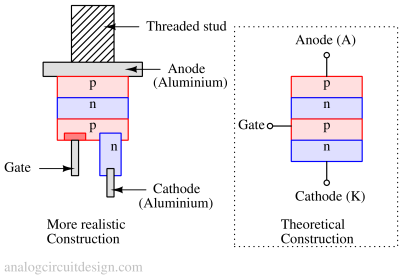
Anode (A): The anode is the positive terminal of the thyristor. It is made of a heavily doped P-type semiconductor material. The anode terminal allows for the injection of current into the thyristor.
Cathode (K): The cathode is the negative terminal of the thyristor. It is made of a heavily doped N-type semiconductor material. The cathode terminal is where the output current flows out of the device.
Gate (G): The gate is a third terminal of the thyristor. It is typically a metallic layer or a P-type material added to one of the N-type layers. The gate is responsible for triggering the thyristor and allowing it to switch from its off state to its on state.

P-N-P-N Structure: The core of the thyristor consists of four semiconductor layers arranged in the following order: P-N-P-N. This forms two P-N junctions inside the device, known as the anode-cathode junction (A-K) and the cathode-anode junction (K-A).
Current-Voltage characteristics of a Thyristor

Principle of operation
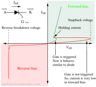
To turn the thyristor on, a positive voltage pulse is applied to the gate (G) terminal. This voltage pulse needs to be of sufficient magnitude to trigger the device. When the gate is triggered, it allows a small current to flow into the base of the P-N-P transistor within the thyristor structure.
The small current injected into the base of the transistor triggers a regenerative action. It causes the transistor to turn on, allowing a large current to flow from the anode to the cathode. Once the thyristor is turned on, it latches into the conducting state even after the gate voltage is removed. This is due to positive feedback, and the thyristor remains in the on state until the anode-cathode voltage drops below a certain threshold or a reverse voltage is applied.
How to turn-off a thyristor ?
To turn off the thyristor, the anode-cathode current must be reduced below the holding current, or a reverse voltage is applied to the device. This is called commutation. Once the current falls below the holding current or a reverse voltage is applied, the thyristor turns off, and the flow of current is blocked.