Torque of a DC motor
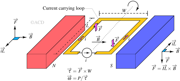
When a DC machine operates under load, whether functioning as a motor or a generator, the rotor's conductors carry current within the magnetic field of the air gap. Consequently, each of these conductors undergoes a force (F=iL X B) as they are positioned within this magnetic field. These conductors are typically situated near the surface of the rotor at an equal distance from its center. As a result, torque is generated around the rotor's circumference, initiating the rotation of the rotor.

Basic model of a DC motor
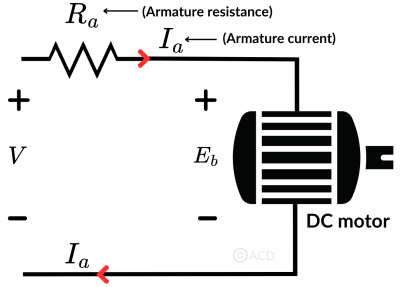
To derive the torque equation, we'll start by examining the fundamental circuit diagram of a DC motor and its corresponding voltage equation.

In the above diagram, V represents the supply voltage, Eb stands for the generated back electromotive force, and Ia and Ra denote the armature current and armature resistance respectively, the voltage equation can be expressed as follows:
$$V=E_b+I_aR_a$$
Torque equation of DC motor : Method 1
From Fig 1, we can derive the torque directly for a DC motor,
$$\overrightarrow{F}=\overrightarrow{iL}\times{}\overrightarrow{B}$$
Total Torque on a single armature winding,
$$\overrightarrow{\tau{}}=\overrightarrow{iL}\times{}\overrightarrow{B}\times{}\overrightarrow{W/2}$$
$$\tau{}=i\cdot{}B\cdot{}L\cdot{}(W/2)$$
Total Torque on a Z number of armature windings,
$$\tau{}=i\cdot{}B\cdot{}L\cdot{}(W/2)\cdot{}Z$$
B is the magnetic field at a distance W/2 from the axis of rotation and Ia is the armature current. DC motor has A parallel paths of armature windings simultaneously connected to the brush via a commutator. So, the current in each armature winding connected to the brush is :
$$i=\cfrac{I_a}{A}$$
Suppose there are P number of magnetic poles and each pole has flux equal to φ, so the magnetic field (B) can be substituted by measuring the total flux generated by P-poles per unit area. The force is generated from W/2 distance from the center on the conductor length of L. So, magnetic field B, which is flux per area is :
$$B=\cfrac{P\phi{}}{2\pi{}(W/2)L}$$
Substituting B and i in torque equation:
$$\tau{}=\cfrac{I_a}{A}\cdot{}\cfrac{P\phi{}}{2\pi{}}\cdot{}Z=\cfrac{PZ\phi{}I_a}{2\pi{}A}$$
So, the torque is proportional to the armature current (Ia) and magnetic flux per pole and number of poles.
Torque equation of DC motor : Method 2
In this method, we shall use Back EMF to calculate the power and torque of a DC motor. Torque is dependent on available power for the rotation of the motor. Thus, employing the aforementioned equation to derive input power, armature power loss, and available power for rotation, we will multiply both the left-hand side (LHS) and right-hand side (RHS) by Ia :
$$VI_a=E_bI_a+I_a^2R_a$$
Currently, Ia2Ra represents the power loss resulting from armature coil heating. The genuine effective mechanical power needed to generate the desired torque in a DC machine is expressed as follows:
$$P=E_bI_a$$
As mentioned in Figure 1, the relationship between Power (P), Torque (τ), and Rotation speed (angular speed, ω):
$$P=\tau{}\omega{}$$
Equating the above two equations,
$$\tau{}\omega{}=E_bI_a$$
So, torque (τ):
$$\tau{}=\cfrac{E_bI_a}{\omega{}}$$
Substituting expression of back emf of DC motor into the above equation:
$$E_b=\cfrac{P\phi{}ZN}{60A}$$
Where Eb is the induced emf of the motor known as Back EMF, A is the number of parallel paths through the armature between the brushes of opposite polarity. P is the number of poles, N is the speed (in rpm), Z is the total number of conductors in the armature and φ is the useful flux per pole.
$$\omega{}=\cfrac{2\pi{}N}{60}$$
Substituting the value of ω and Eb into the torque (τ) equation, we get:
$$\tau{}=\cfrac{PZ\phi{}I_a}{2\pi{}A}$$