Transformer impedance transformation
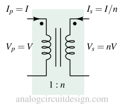
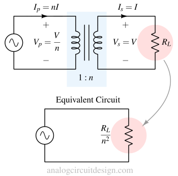
When a load (R) is connected to the secondary side of the transformer, depending on the turns-ratio (1:n), the effective load that appears to the source connected in the primary side can be represented as (1/n2) of the load connected to the secondary side.
This is due to the conservation of power between primary and secondary winding.
$$V_PI_P=V_SI_S$$

Equivalent circuit representation

As the figure mentioned, the secondary side has load resistance of RL. Because of the power conservation on the secondary-primary side and the turns ratio, the impedance can be represented as RL/n2 in the primary side alone without having the secondary side. This is for simplify the analysis. The equivalent circuit is consistent with the following equations.
$$\cfrac{N_P}{N_S}=\cfrac{V_P}{V_S}=\cfrac{I_S}{I_P}=\sqrt{\cfrac{Z_P}{Z_S}}=\cfrac{1}{n}=\cfrac{1}{\text{Turns ratio}}$$
Example
If a transformer has a turn ratio of 1:5 (n=5) and load resistance RL\=10 Ohms, then what would be the equivalent resistance seen from the primary side of the transformer?
$$\sqrt{\cfrac{Z_P}{Z_S}}=\sqrt{\cfrac{Z_P}{10}}=\cfrac{1}{5}$$
$$\implies{} Z_P=\cfrac{10}{25}=0.4\Omega{}$$