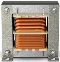
Transformers Basics
Transformers are passive elements that step up or step down voltages or currents with input power equal to output power. However, because of imperfections, like nonidealities, some power is lost, and the output power ends up being less than the input power. Transformers work for AC voltage only. It acts as a short circuit for DC voltage, and the current is only limited by the last resistance offered by the conductor.

Transformers are essential for adjusting voltage levels in power lines, ensuring electricity can be transmitted over long distances without significant losses, and then reducing voltage for safe use in homes and businesses. Small transformers are found in devices like adapters and chargers for electronics, including laptops, phones, and other appliances.
Working principle of a transformer

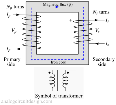
A current in any transformer coil (primary side) produces a magnetic flux in the transformer's core (Biot-Savart law). Suppose the flux is varying due to varying currents in the coil. In that case, it induces a varying voltage (Faraday's law of induction) across any other coil wound (secondary side) around the same core. Since all the windings are seeing the same change in flux and are connected in series, the total voltage induced is the sum of all the voltages produced in each winding.
Following Lenz's law, the secondary current produced creates a flux equal to and opposite to that produced by the primary winding. The polarity of the secondary winding with respect to the primary winding is denoted by dot notation.
Electrical energy can be transferred between separate coils without a metallic (conductive) connection between the two circuits. The load impedance referred to the primary circuit equals the turns ratio squared times the secondary circuit load impedance.
Transformer equations
Using energy conservation, the power on the primary side is equal to that on the secondary side.
$$\text{Power}_{\text{Primary}}=\text{Power}_{\text{Secondary}}$$
Using Faraday's law of induction,
$$\cfrac{V_p}{N_p}=\cfrac{V_s}{N_s}=\cfrac{d\phi{}}{dt}$$
Step-up transformer
A step-up transformer increases the voltage level from the primary winding to the secondary winding. The number of turns in the secondary winding is greater than in the primary winding.
$$N_p<N_s$$
$$V_p<V_s$$
$$I_p>I_s$$
Step-down transformer
A step-down transformer decreases the voltage level from the primary winding to the secondary winding. The number of turns in the secondary winding is fewer than the number of turns in the primary winding.
$$N_p>N_s$$
$$V_p>V_s$$
$$I_p<I_s$$
Ideal transformer
An ideal transformer has the following properties :
- It is linear - The magnetic core does not saturate.
- It is lossless - No I2R power loss because of zero resistances in the conductors. There are no hysteresis losses as well. This means it is 100% efficient.
- The primary and secondary sides are perfectly coupled - This means infinitely high magnetic permeability of the core and no flux loss in the air.
Losses in a real transformer
Real transformer deviates from ideal transformer due to following reasons:
Magnetic core losses
The magnetic core is a soft-iron material which can be easily magnetized and demagnetized. It has the ability to concentrate the magnetic field lines. However, as with any material, it is also prone to losses as listed below :
Hysteritic losses
When the magnetic core is exposed to a changing magnetic field, its magnetic domains reorient themselves to align with the direction of the field. As the field changes direction, these domains need to rearrange, which involves overcoming the inherent resistance within the material. Extra energy is required to overcome the resistance of the material.
Eddy current losses
The magnetic core, in the presence of a varying magnetic field, experiences electromagnetic induction. This induces circulating currents, known as eddy currents, within the material. These currents circulate in closed loops and can create their magnetic fields, which oppose the original magnetic field that caused them. The material's resistance to the flow of these eddy currents leads to the conversion of electrical energy into heat energy, resulting in energy losses.
Winding losses
Joule losses (or Copper losses)
A transformer's primary and secondary windings are typically made of copper wires. Copper is a good conductor of electricity but still has some resistance. When current flows through these windings, a portion of the electrical energy (I2R) is converted into heat due to the resistance of the copper wires.
Leakage flux
In a real transformer, the magnetic flux does not follow the intended path through the transformer's core. This flux, which does not link to the secondary side, is called leakage flux. The leakage flux does not contribute to energy transfer between the windings; it leads to energy loss and reduces the efficiency of the transformer.
The leakage flux induces eddy currents in nearby conductive components, including the windings, leading to localized heating and additional energy loss. It can also induce stray magnetic fields that may interfere with nearby electronic devices.
Effect of load on energy losses
Hysteresis and eddy current losses are constant at all load levels and dominate at no load while winding loss increases as load increases. The no-load loss can be significant, so even an idle transformer constitutes a drain on the electrical supply.
Transformer ratings
The transformer's rating is the maximum voltage and current that can be safely applied to the transformer. The rating could be improved in the presence of an effective cooling system. The requirement of a cooling system is dependent on transformer losses.
Usually, transformers are rated in kVA (kilo-volt-ampere). To know more about why these are rated in kVA, please visit this page: Why is a transformer rated in KVA, not KW?
Effect of transformer's operating frequency
The EMF is proportional to the rate of change of flux. So, with an increase in frequency, the EMF per turn can be increased. So, same voltage can be achieved with lesser number of turns at higher frequency. Therefore, sometimes, to make a transformer compact (less number of turns), it is operated at a higher frequency. Aircraft and military equipment employ 400 Hz power supplies, reducing core and winding weight.
However, with higher operating frequencies, core loss, and conductor skin effect also increase.
Circuit representation of a real transformer

In the transformer model shown, the winding joule losses and leakage flux reactance in shown by RP, XP (Primary resistance and reactance) and RS, XS (Secondary resistance and reactance). Core losses are represented using shunt elements RC and XM
Efficiency of a transformer
Efficiency (η) :
$$\eta{}=\cfrac{\text{Output power}}{\text{Input power}}$$
$$\eta{}=\cfrac{\text{Input power - Losses}}{\text{Input power}}$$
$$\implies{}\eta{}=1-\cfrac{\text{Losses}}{\text{Input power}}$$
What is an isolation transformer?
An isolation transformer is a type of transformer that is designed to transfer electrical power from one circuit to another while providing galvanic isolation between the two circuits. All the transformers we use in transmission and distribution networks having isolated primary and secondary windings are called isolation transformers. In fact, this article focused on isolation transformers only. There is another type of transformer that is not isolated called an Autotransformer.
How isolation in a transformer work?
The primary function of an isolation transformer is to reduce voltage spikes in the supply lines due to lightning, static electricity, or sudden changes in voltage usage. It affects the electrical power supply lines to produce voltage spikes, transients, and surges. The voltage spike is a sudden rise in the voltage levels (several volts to several thousand volts), which lasts for a very short duration (~ nanoseconds to microseconds).
When a very short-duration voltage spike is applied at the primary winding, it tries to increase the current on the primary side. Since the inductor opposes the sudden change in the current, it doesn't allow the change in current instantaneously but changes linearly with time. This linearly varying current will induce flux in the magnetic core and a voltage in the secondary winding. Since the change in primary current is slow for the voltage spike, the voltage induced in the secondary will also be less.
Intuitively, the inductors form a low-pass RL filter. R is the load, and L is the inductance of the transformer.
FAQs
Why can't transformers operate on DC voltage?
Transformers cannot operate with DC voltage because they require a changing magnetic field to induce a voltage on the secondary side. When DC voltage is applied to the primary side, it creates a constant magnetic flux in the core. This constant flux cannot induce a voltage on the secondary side. Applying DC voltage to the primary side also results in significant current demand due to zero reactance.