Translinear Circuits: How Exponential Current Relationships Are Used
What is Translinear principle?
The word translinear refers to the property of bipolar transistors (BJTs) where the transconductance of a BJT varies linearly with its collector current. This relationship stems from the logarithmic connection between the collector current and the base-emitter voltage.
$$V_{be}=V_t\ln{\cfrac{I_c}{I_s}}$$
$$\cfrac{dI_c}{dV_{be}}=g_m=\cfrac{I_c}{V_t}$$
Translinear principle according to Barrie Gilbert (Original author) - In a closed loop containing an even number of forward-biased junctions, arranged so that there are an equal number of clockwise-facing and counterclockwise-facing polarities, the product of the current densities in the clockwise (CW) direction is equal to the product of the current densities in the counterclockwise (CCW) direction.
According to Bradley A Minch (Renowned IC design professor) - "Gilbert also meant the word translinear refers to circuit analysis and design principles that bridge the gap between the familiar territory of linear circuits and the uncharted domain of nonlinear circuits."
Translinear components
For the translinear principle to be applicable, the device must follow exponential I-V characteristics. Some devices which follow the exponential I-V characteristics are :
- The bipolar transistor
- The diode
- The MOS transistor in weak inversion
Translinear analysis method
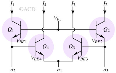
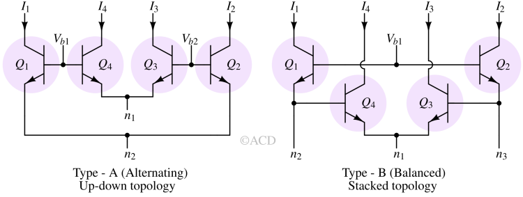
When four closely matched npn bipolar transistors are arranged in a closed loop (Fig 2) of base-emitter junctions and biased in the forward-active region at the same temperature, Kirchhoff’s voltage law (KVL) suggests that (In the analysis, we have neglected both base currents and Early effect.) :
$$V_{BE1}+V_{BE4}=V_{BE3}+V_{BE2}$$
$$V_t\ln{\cfrac{I_1}{I_s}}+V_t\ln{\cfrac{I_4}{I_s}}=V_t\ln{\cfrac{I_3}{I_s}}+V_t\ln{\cfrac{I_2}{I_s}}$$
$$\ln{\cfrac{I_1I_4}{I_s^2}}=\ln{\cfrac{I_3I_2}{I_s^2}}$$
$$I_1I_4=I_3I_2$$
This outcome represents a specific instance of Gilbert’s translinear principle (TLP), where the multiplication of the currents flowing clockwise equals the multiplication of those flowing counterclockwise.
Applications of translinear circuits
- (Controllable) amplifiers
- Current mirror
- Current amplifier
- Non-linear signal processing functions
- Multiplication/division
- RMS-DC conversion
- Vector summation
- Squaring and square-rooting
- Low-voltage and low-power circuits
Examples of translinear circuits
Listed below are various examples of translinear circuits, each designed to generate distinct and intriguing nonlinear outputs.
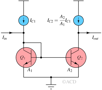
Current mirror and amplifiers
Single quadrant multiplier
Geometric mean circuit
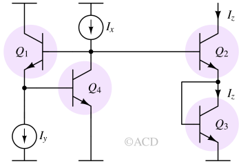
$$I_z^2=I_xI_y$$
Squaring circuit
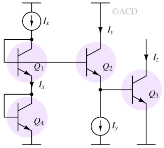
$$I_z=\cfrac{I_x^2}{I_y}$$
Vector addition circuit or Pythagorator
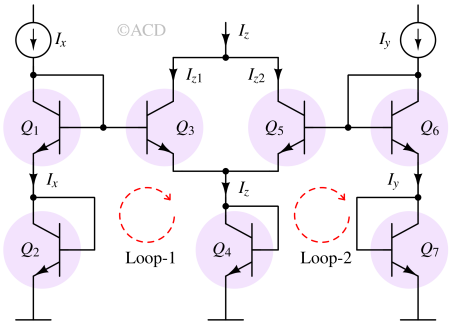
Translinear loop-1 :
$$I_x^2=I_{z1}I_{z}$$
Translinear loop-2 :
$$I_y^2=I_{z2}I_{z}$$
Adding both the equations :
$$I_x^2+I_y^2=(I_{z1}+I_{z2})I_{z}=I_z^2$$
Reference
- Original paper from Barrie Gilbert - "Gilbert, B., 1975. Translinear circuits: A proposed classification. Electronics Letters, 1(11), pp.14-16."
- A presentation from B Minch - Translinear Circuits
- Video recording by the Original Author (Barrie Gilbert).