Triac
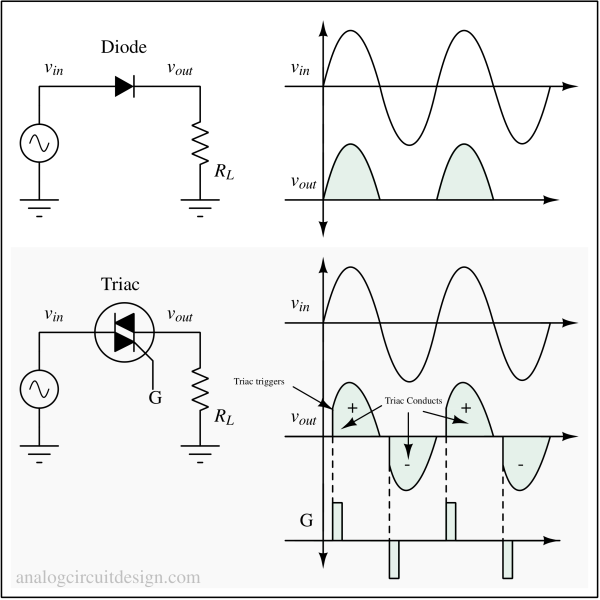
Triacs are 3-terminal devices used to control the RMS voltage of load when the input is an AC voltage. These are connected in series between the AC supply and the AC load. Since Triacs are bidirectional devices, they are not used as rectifiers (AC to DC conversion). For rectification, SCRs are used instead.
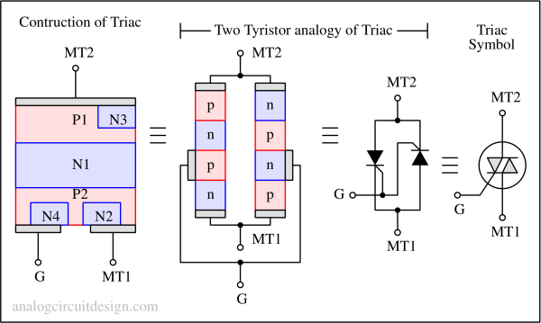
Symbol and Construction of Triac

Since Triac is a bidirectional device, terms like anode and cathode are not used for it. It resembles two SCRs connected in inverse parallel with a common gate terminal in a single piece of semiconductor.
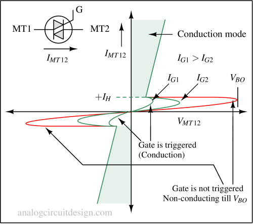
Expectation from a ideal Triac is that it would be a symmetric device. It's forward and reverse I-V characteristics should be identical. However in reality, the forward and reverse voltage characteristics (breakdown voltages, trigger voltage, holding current) are different due asymmetry of the device.
Operation of Triac

There are 4 modes in which the triac can be conducting. This is primarily due to sharing of doping regions and asymmetry of the device:
- Mode I+: V(MT12) > 0 and Gate current being positive
- Mode I-: V(MT12) > 0 and Gate current being negative
- Mode III+: V(MT12) < 0 and Gate current being positive
- Mode III-: V(MT12) < 0 and Gate current being negative
The trigger current sensitivity is highest for Mode I+ and III-.
I-V Characteristics of a Triac

If gate terminal is open, the Triac won't turn on till VBO is reached. It is turned on by pushing or pulling a gate current. If the gate current is higher, the on-voltage (VON) is lesser. If the current falls below the holding current (IH), then the Triac is again in turned-off state.
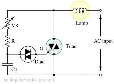
Triac control circuit

The input phase is controlled by (VR1+R)*C1 network. When the phase shifted voltage crosses the threshold of Diac (VBO), the Diac triggers (and the capacitor discharges through Diac) which triggers the Triac and lamp turns on. Since the passives VR1, R, C1 are bidirectional devices, the same phase-shifting works for the opposite polarity also.
Advantages and disadvantages of Triac
Advantages
- It allows conduction in both the direction.
- It requires single fuse for protection
- Reverse bias breakdown is avoided because a parallel conducting diode is always present.
Disadvantages
- Gate triggering circuit is bit complex in comparision to SCR.
- Not as reliable as compared to SCR when connected to inductive loads (like motors).
- Lower voltage ratings in comparision to SCR.
Due to the disadvantages of a Triacs while driving inductive loads, inverse parallel SCR pairs are preferred over Triac.
Applications of Triac
It is used to control the RMS voltage of AC load by controlling the conduction phase.
- Fan speed regulator
- AC Lamp dimmer
- AC voltage stabiliser
- Thermostat