Vector Network Analyzer
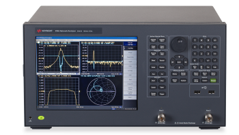
A Vector Network Analyzer (VNA) is an electronic test instrument used to measure the electrical properties of RF and microwave components, such as s-parameters, filter's transfer function, gain, insertion loss, return loss, impedance, etc. VNAs are used for characterizing components like antennas, filters, amplifiers, cables, and connectors.

Key functionalities of Vector network analyser
Magnitude and phase measurements
VNA can measure both amplitude and phase, which is unique and more sophisticated than spectrum analyzers. Phase measurement allows to measure the capacitive or inductive nature of the device across frequencies. It allows to draw smith chart, reflection parameters which needs phase information.
S-parameter measurement
S-parameters, also known as scattering parameters, provide crucial information about the reflection and transmission properties of the device under test (DUT). Common parameters of interest include return loss (|S11|), insertion loss (|S21|), isolation (|S12| and |S22|), and phase information. The VNA generates a known test signal and sends it to the DUT through connectors and cables. The VNA measures the response of the DUT and compares it with the incident test signal capturing both magnitude and phase information.
Performing accurate S-parameter measurements requires careful calibration and attention to details such as cable lengths, connector types, and environmental conditions.
Reflection parameters
Reflection parameters, often called reflection coefficients or S11 parameters, are essential measurements in RF (radio frequency) and microwave engineering. They provide information about how a device or component reflects an incident electromagnetic wave when it encounters a discontinuity or impedance mismatch.
The relationship between reflection coefficient Γ, the amplitude of the incident wave (Vinc), and the amplitude of the reflected wave (Vref) is :
$$\Gamma{}=\cfrac{V_{reflected}}{V_{incident}}=\cfrac{Z_L-Z_0}{Z_L+Z_0}$$
A zero reflection coefficient indicates no reflection (all power is transmitted through the device), while a reflection coefficient of unity indicates complete reflection (all power is reflected). An impedance mismatch between the transmission line and the connected device will lead to non-zero reflection coefficients, resulting in signal loss, interference, and other undesired effects in RF systems.
Transmission parameters
Transmission parameters, often referred to as transmission coefficients or S21 parameters, are another set of essential measurements in RF (radio frequency) engineering and microwave engineering. These parameters explain how a device or component transmits an incident electromagnetic wave from input to output.
The relationship between reflection coefficient T, the amplitude of the incident wave (Vincident), and the amplitude of the transmitted wave (Vtransmitted) is :
$$T=\cfrac{V_{transmitted}}{V_{incident}}$$
A transmission coefficient of unity indicates that all the power from the incident wave is transmitted through the device, resulting in no loss. A transmission coefficient of zero indicates all the power is lost. A transmission coefficient of less than unity indicates that some power is lost during transmission through the device.
Architecture of modern vector network analyser

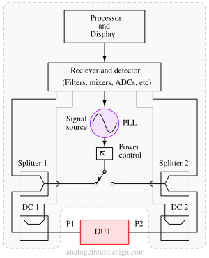
Ports
Ports of VNA are referred to the well-defined electrical connectors where the DUT is connected. Electrically, each port has two terminals: an incident terminal and a reflected wave terminal (usually reference).
For a Two-port VNA :
- Port 1: This is the primary input port where the incident signal is applied.
- Port 2: This is the primary output port where the reflected and transmitted signals are measured.
In a two-port VNA, measurements are focused on the interaction between these two ports, which allows for S-parameter measurements like S11 and S21 (reflection and transmission coefficients, respectively).
Receiver and detector
The receiver measures both the magnitude and the phase of the signal. It needs a reference channel to determine the phase, so a VNA needs at least two receivers.
Signal source
The network analyzer needs a test signal; a signal generator built into a modern network analyzer will provide a known test signal. Some advanced network analyzers have two signal sources to test mixers (RF and LO signals) and intermodulation distortions.
Directional couplers (DC)
Directional couplers are used to sense the reflected, incident, and transmitted waves. These are passive elements based on the principle of power division and isolation between different ports. Each port has one directional coupler.
Splitter
Using an internal mixer, Splitter creates a copy of the incident wave to be compared against the received signal. The retained copy of the incident wave is used to measure the phase.
Processor and display
The receiver section of the VNA converts analog signals into digital values using ADCs. After that, the digital values are processed to convert the data into a human-readable format. Depending on the format requested, the processor converts the data and displays it on a screen.
Calibration of Vector network analyser
Calibration of a vector network analyzer (VNA) is adjusting the VNA’s measurements to correspond to a specific known impedance. The calibration procedure ensures that the VNA’s measurements are accurate and repeatable.
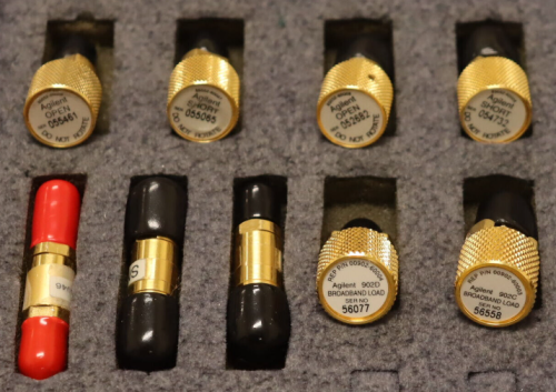
The first step in calibrating a VNA is to measure the impedance of the calibration standard. This can be done using various methods, such as a resistive divider or a load-pull system. Once the impedance of the calibration standard is known, the VNA can be calibrated by adjusting its measurements to match the impedance of the calibration standard (calibration kit).
The calibration procedure for a time-domain or frequency-domain VNA typically involves sweeping the device through its measurement range and comparing the results to a known standard. The VNA is typically calibrated at several points throughout its range, and the results are averaged to produce a calibration curve.

Some good source to learn calibration of VNA
Difference between Vector network analyzer and Spectrum analyzer
| Vector Network analyser | Spectrum analyser |
|---|---|
| Magnitude and Phase measurements | Magnitude measurements only |
| A known test signal is generated by the instrument | No test signal is generated. DUT itself should generate signal. |
| S-parameters, Return and insertion loss, Filter transfer function, Reflection | Spectrum (Signal or carrier level vs frequency), sidebands, harmonics, phase noise |
| Smith charts, polar plots, and logarithmic or linear magnitude and phase plots | Frequency vs. amplitude plot, sometimes with markers and peak detection features |
Low cost Affordable Vector Network Analyzers
Few low cost known VNA are listed below (Source - Reddit, x.com etc. These not sponsored) :