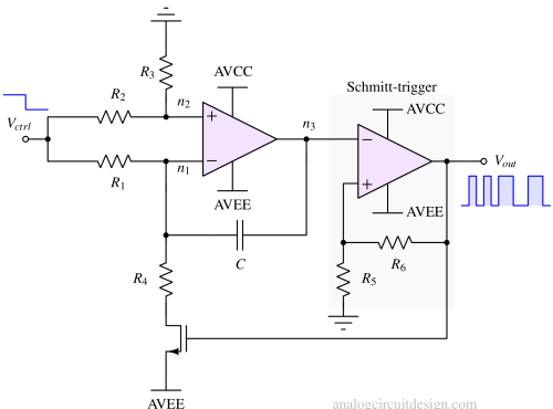
Voltage controlled oscillator (VCO)
A voltage-controlled oscillator (VCO) is an electronic oscillator whose output frequency is determined by an input voltage. Frequency is the rate at which the phase changes. A voltage-controlled oscillator enables adjustments to this phase change rate. Usually, VCOs are derived from known oscillator circuits. Various applications include telecommunications, signal modulation, PLLs, and synthesizers.
Working Principles of VCO
A widely used type of VCO is the LC oscillator-based VCO. The core principle of the LC oscillator is explained here. To convert it into a VCO, a varactor diode is added to the circuit. Changing the reverse bias voltage across the varactor can adjust its capacitance and, consequently, the oscillation frequency. Some other alternatives of varactor diodes are MOScap, CB-junction of BJT, etc.
High frequency synthesizer using VCOs and PLL
Generation of accurate high-frequency signals is a challenge because :
- Crystal oscillators may be very accurate but incapable of creating frequency above the GHz range.
- VCOs can produce high-frequency signals, but they lack accuracy. Their frequency is highly sensitive to changes in time, temperature, and voltage, making them impractical without corrective measures.
So, to provide the best of both worlds, the VCO accuracy is corrected by putting it in the feedback loop and the crystal oscillator is chosen as a reference.
Working principle of VCOs in Phase Locked Loop
When the output frequency deviates from a desired value (also called the reference clock), feedback mechanisms adjust the control voltage to correct this deviation. For instance, if the output frequency increases due to temperature changes affecting transistor characteristics, the feedback loop reduces the control voltage, lowering the output frequency back to its target.
Key components of a VCO circuit
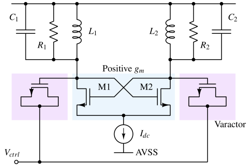
A VCO (Voltage-Controlled Oscillator) circuit typically consists of the following key components:
- Resonator or Tank Circuit: Made of inductors and capacitors, it determines the frequency range of the VCO.
- Amplifier and Feedback network: Used to maintain the oscillations by compensating for any losses in the circuit. In an LC oscillator, it creates a negative gm. This negative gm cancels the dissipative resistor in the circuit.
- Voltage-Controlled Element: This could be a varactor diode, a transistor, or another component changing capacitance with varying input voltage.
- Output Buffer: Often used to isolate the VCO from the load to prevent the load from affecting the oscillation frequency.
Types of Voltage-Controlled Oscillators
Based on the output waveform generated
- Linear (Harmonic) voltage controlled oscillator
- Relaxation voltage controlled oscillator
| Properties | Linear (Harmonic) VCO | Relaxation VCO |
|---|---|---|
| Principle of Operation | Based on energy exchange between two reactive components (e.g., an inductor and a capacitor in electrical systems, or a mass and a spring in mechanical systems). | Based on the periodic charging and discharging of a capacitor through a resistor or other nonlinear elements. |
| Region of operation of the active element | Operates in the linear region of the system, where the restoring force or voltage is proportional to displacement or charge | Operates in the nonlinear region, with abrupt transitions between two states. Relies on threshold triggering (e.g., a transistor switching states between cut-off and saturation region) |
| Waveform | Produces smooth, sinusoidal waveforms | Produces non-sinusoidal waveforms such as square waves, triangular waves, or sawtooth waves |
| Frequency determination | Frequency is determined by the natural resonance of the system. So, it does not depend on transistor parameter, supply voltage. Only dependent on inductor and capacitor. | Frequency depends on the time constants of the charging and discharging process. Frequency may be dependent on supply voltage. |
| Components needed | Requires inductors and capacitors (LC oscillators), crystals (crystal oscillators), or RC circuits for frequency stability | Typically uses resistors, capacitors, and active devices like transistors, op-amps, or Schmitt triggers. |
| Applications | Used in radio transmitters, clocks, and systems requiring high-frequency stability | Used in timing circuits, waveform generators, flashing lights, and low-frequency signal generation |
Based on components used
- RC VCO
- LC VCO
- Ring oscillator-based VCO
- Crystal VCO
| Property | RC-VCO | LC-VCO | Ring Oscillator | Crystal-VCO |
|---|---|---|---|---|
| Oscillation Mechanism & Frequency | Based on RC network time constants, it supports lower frequencies. | Based on LC resonance, it achieves higher frequencies. | It uses a chain of inverters or delay stages and supports a wide frequency range. | Based on crystal resonance, it operates at fixed or narrow frequency ranges. |
| Stability & Noise | Less stable, higher phase noise. | More stable, lower phase noise. | Moderate stability, relatively higher phase noise. | Extremely stable with very low phase noise. |
| Design & Integration | Simple design, smaller size, easy to integrate into ICs. | Complex design, larger size, harder to integrate, takes significant area inside an integrated circuit. | Very simple, compact, highly IC-compatible. | Larger size due to crystal. Usually, it is not integrated into a single substrate. However, it can be accommodated into the same package. |
| Tuning & Applications | Wider tuning range; used in low-frequency oscillators. | Limited tuning range; used in RF communication. | Wide tuning range; ideal for digital applications (e.g., clock generation). | Minimal tuning is used in precise timing applications like clocks and radios. |
| Power & Performance | Low power, lower Q factor, moderate performance. | Higher power, higher Q factor, better selectivity. | Low power, low Q factor, moderate performance. | It has low power, a very high Q factor, and exceptional performance. |
Performance Metrics of VCO
Following are the key performance metrics for a VCO :
Tuning range
The tuning range is typically expressed as a percentage of the center frequency. For example, a VCO with a center frequency of 10 GHz and a tuning range of 2 GHz would have a tuning range of 20%.
Phase noise
Phase noise quantifies the short-term frequency fluctuations of an oscillator, impacting signal quality and system performance. Read more about phase noise - Phase noise.
Power consumption and efficiency
Achieving low-phase noise, and a higher tuning range typically requires higher power consumption. For example, circuits designed for optimal phase noise performance often utilize higher bias currents or more complex architectures that inherently draw more power.
Mathematical model of voltage-controlled oscillator
The mathematical model of a VCO can be expressed as follows:
Frequency vs. control voltage characteristics
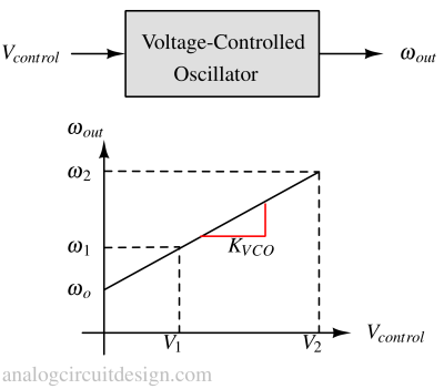
$$f_{out}=K_{VCO}(V_{ctrl}-V_o)+f_o$$
where:
fout = Output frequency of the VCO, f0 = Free running frequency of the VCO (when Vctrl=Vo), KV = VCO gain (Hz/V), Vctrl = Applied control voltage, V0 = Control voltage corresponding to free-running frequency. When Vctrl terminal is floating.
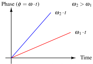
The transfer function of a VCO
$$\omega{}=\cfrac{d\phi{}}{dt}$$
$$\phi{}=\int{}\omega{}\cdot{}dt+\phi{}_o$$
$$V_{out}=V_o\cos{\underbrace{\left(\omega{}_ot+2\pi{}K_{VCO}\int{}V_{ctrl}dt\right)}_{\text{Phase}}}$$
$$\phi{}_t(t)=\omega{}_ot+2\pi{}K_{VCO}\int{}V_{ctrl}dt$$
Excess Phase :
$$\phi{}_e(t)=2\pi{}K_{VCO}\int{}V_{ctrl}dt$$
$$\cfrac{\phi{}_e(s)}{V_{ctrl}(s)}=2\pi{}\cfrac{K_{VCO}}{s}$$
Phase noise and jitter
An ideal oscillator produces a perfect sine wave. In the frequency domain, this corresponds to a delta function located at the oscillator's frequency, meaning all the signal's power is concentrated at one frequency. In contrast, real oscillators exhibit phase-modulated noise components, distributing the signal's power to neighboring frequencies. Phase noise represents these rapid, short-term, random fluctuations in the phase of a waveform, arising from time-domain instabilities or jitter.
Mathematical definition of Phase noise: Phase noise is defined as the noise power in a 1 Hz bandwidth at a specified frequency offset from the carrier frequency. It is typically expressed in decibels relative to the carrier (dBc/Hz) and is measured at various offsets, commonly 1 kHz or 1 MHz from the carrier frequency.
The Leeson model is commonly used to predict phase noise behavior in VCOs. It accounts for thermal and flicker noise contributions and introduces parameters such as the resonator's quality factor (Q) and the device's noise floor.
LC oscillator based VCO
LC oscillators are voltage-controlled oscillators (VCOs) that utilize inductors (L) and capacitors (C) to generate oscillating signals. They are widely used in radio frequency (RF) applications due to their low phase noise and ability to provide stable frequency outputs. Tunability of frequency is achieved utilizing a varactor. The varactor is constructed using MOSFET. 
$$\omega{}_{osc}=\cfrac{1}{\sqrt{L_1(C+C_{GB})}}$$
$$C=C_1=C_2$$
$$K_{VCO}=\cfrac{d\omega{}_{out}}{dC_{GB}}\cdot{}\cfrac{dC_{GB}}{dV_{VDD}}$$
$$C_{GB}=\cfrac{C_{GB0}}{(1+V_{DD}/\phi{}_B)^m}$$
$$K_{VCO}=\cfrac{C_{GB}}{C+C_{GB}}\cdot{}\cfrac{m}{2\phi{}_B+2V_{VDD}}\cdot{}\omega{}_{osc}$$
Varactor
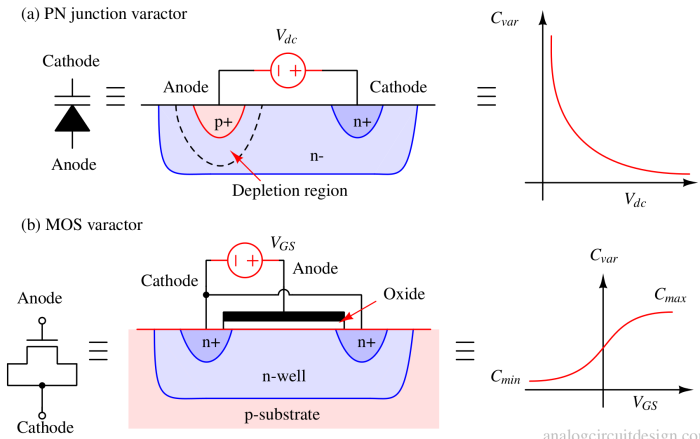
Varactor is a short form of Variable-capacitor. There are primarily two types of Varactors available. PN junction varactor (also called varactor diode) and MOS varactor.
A varactor-diode is a diode whose internal capacitance varies with the variation of the reverse voltage applied across it. It operates exclusively in reverse bias, where no current flows through the device, allowing it to function as a voltage-controlled capacitor.
Applications of VCOs
- VCOs are crucial components in PLLs, which are used to generate high-frequency clocks while maintaining the accuracy of the reference (quartz crystal).
- Use in frequency modulation (FM) and synthesis - The control voltage can be connected to the message signal. The output frequency will be modulated based on the message signal.
- Microcontrollers and clocks - VCOs are used internally inside a microcontroller to provide a high-frequency internal clock. VCOs are part of the internal PLL block inside a microcontroller. The reference frequency is taken from a slower but precise external quartz crystal oscillator.
- Synthesizers - In music technology, VCOs generate waveforms whose pitch can be controlled by varying the input voltage, allowing for musical note generation
Relaxation oscillator VCOs
Ring oscillator (inverters) based VCOs
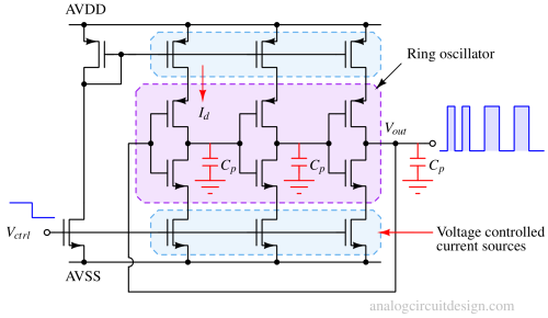
Noise in the system will initiate oscillation. The oscillation frequency is set by the single inverted delay (Td). Td is the function of the current drive and the capacitance of each stage. Between the rising and falling edge of the signal at each node, the signal has propagated through 3 inverters. So, half time-period is 3Td, and the full-time period is 6Td.
More about Current Starved Ring Oscillators : Ring oscillators
Timer 555 based voltage controlled oscillator
Triangular wave voltage controlled oscillator
