Voltage integrator
A voltage integrator integrates input voltage with respect to time. If the input is DC voltage, the output will continue to rise at the rate defined by the resistor and capacitor used in the circuit. It replicates mathematical integration. The output voltage not only depends on the input voltage magnitude but also on the time duration.
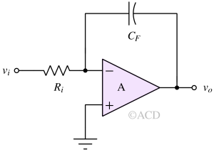
The output voltage expression for a basic op amp voltage integrator is mentioned below:
$$v_o(t)=-\int_{-\infty{}}^{t}\cfrac{v_i}{R_iC_F}dt$$
Opamp integrator characteristics
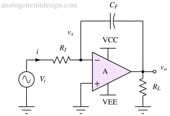
Deriving transfer function of voltage integrator
Applying KCL at node vx,
$$\cfrac{v_i-v_x}{R_I}+\cfrac{v_o-v_x}{1/sC_F}=0$$
We have assumed that the current going into the inverting terminal of the opamp is zero due to the infinite impedance offered by the ideal op-amp.
$$v_x=-\cfrac{v_o}{A}$$
Since the gain (A) offered by an ideal amplifier is infinite we can assume vx=0. Therefore,
$$\cfrac{v_o}{v_i}=-\cfrac{1}{sRC}$$
DC characteristics of integrator
In DC, the capacitor in the feedback path can be assumed to be absent. So, the amplifier is in an open loop. The output voltage of an opamp integrator is saturated to the supply rails because of the opamp's very high gain multiplied by the amplifier's systematic/random offset. In saturation, op amp does not work as desired.
To get the desired functionality, it is required to add some negative feedback in DC itself so that the output does not saturate. That is why resistive feedback is added to stabilize the output to the desired voltage.
AC response of integrator
Assuming that the output of the opamp used in the integrator is not saturated to supply rails, the transfer function of an integrator is (in the Laplace domain) :
$$\cfrac{v_o(s)}{v_i(s)}=-\cfrac{1}{sRC}$$
Frequency (ω) response is:
$$\cfrac{v_o(s)}{v_i(s)}=-\cfrac{1}{j\omega{}RC}$$
Bode plot of an ideal integrator: The gain is infinite at DC (s=0). The gain is decreasing at -20dB/dec. This means the gain is falling 10 times for every 10 times rise in frequency.
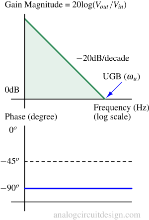
The phase plot shows that the phase lags by 90° throughout the frequency range. This also means that the circuit introduces a delay if used in control systems.
Transient response of integrator
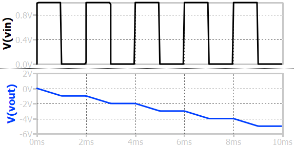
In transient, if a step voltage is applied, the output will ramp till it saturates to the supply voltage. If a square periodic pulses are applied at the input (between 0 and 1), the output will have slope-staircase behavior. The output keeps on decreasing because the current never reverses its direction through Ri. The square wave voltage is always positive.
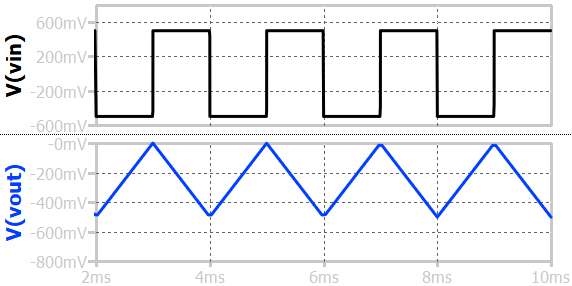
If the square periodic pulses have a voltage symmetric across y=0, the output will be a triangular wave. For 50% of the time, the voltage is positive and the current through Ri will charge the capacitor. For the rest 50% of the time, the voltage is negative and the current through Ri will discharge the capacitor by the same amount. So, the voltage will come back to its original value. That is how the triangular waveform is formed.
Non-ideal properties of voltage integrator
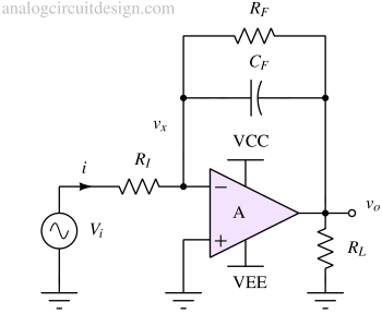
In a standalone integrator circuit, the output voltage saturates due to the opamp's high gain and offset voltage. If the opamp saturates, the integrator circuit does not work as intended. So, a feedback resistor RF is required to define the output voltage. Now, the output voltage is :
$$V_{out}=-\cfrac{R_F}{R_I}V_i+V_{os}\left(1+\cfrac{R_F}{R_I}\right)$$
Usually starting point of every circuit is zero. So, if Vi is zero, the output is :
$$V_{out}=V_{os}\left(1+\cfrac{R_F}{R_I}\right)$$
Vos is the order of a few mV. Let's assume Vos is 1mV and RF/RI is 100. So, Vout is at 100mV. If the supply voltage is +-5V (VCC = +5V and VEE = -5V), we see that the output voltage is near mid-supply. This is a good operating point for most of the amplifiers.
The amplifier now is in its proper operating condition and ready to behave like an integrator.
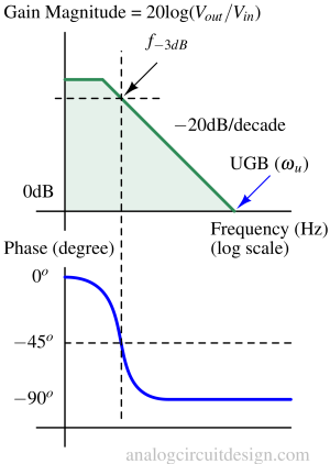
The finite gain integrator's bode plot is mentioned above. With resistor RF, the gain is limited to RF/RI at DC which is visible in the plot. The gain before f-3dB saturates to RF/RI. This is different from the plot of ideal integrator, where the gain never saturates.
Applications of opamp integrator
Following are the some examples of voltage integrator:
Ramp generator
A ramp generator is an electronic circuit or system that produces an output signal that ramps up or down in voltage or current over time. It's commonly used in various applications such as waveform generation, motor control, and voltage regulation.
The basic concept involves charging or discharging a capacitor at a constant rate using a current source or sink. As the capacitor charges or discharges, the voltage across it increases or decreases linearly, creating a ramp waveform.
Control systems
In control systems, it is used as an integral controller. The integral controller reduces the steady state error to zero.