Difference amplifier or Voltage subtractor
A difference amplifier (or op-amp voltage subtractor) is an electronic amplifier that amplifies the difference between two input voltages but suppresses any common mode voltage. It has two inputs (Vip and Vim) and one output (Vout).
Difference amplifier circuit diagram

A difference amplifier usually consists of an op amp and four resistors as shown above. Ratio of resistors R2/R1 sets the gain of the difference amplifier.
Difference amplifier voltage gain
An ideal op amp amplifies only the difference between its input terminal Vp and Vm. The common mode (Vp + Vm)/2 is suppressed.
The voltage at terminal Vp can be expressed in terms of Vip as :
$$V_p=V_{ip}\cdot{}\cfrac{R_2}{R_1+R_2}$$
Node voltage Vm can be expressed in terms of Vout and Vim as following :
$$V_{m}=\cfrac{V_{im}R_2+V_{out}R_1}{R_1+R_2}$$
Because of virtual short between nodes Vp and Vm,
$$V_p=V_m$$
$$\implies{}V_{ip}\cdot{}\cfrac{R_2}{R_1+R_2}=\cfrac{V_{im}R_2+V_{out}R_1}{R_1+R_2}$$
$$\implies{}V_{out}=\cfrac{R_2}{R_1}\left(V_{ip}-V_{im}\right)$$
We observe that the output voltage Vout is proportional to difference of the input Vip and Vim with voltage gain factor of R2/R1.
Common mode rejection in difference amplifier
The output depends only on the input difference in an ideal difference or differential amp. The output is zero in a common mode situation (when both inputs are excited by an identical signal). This means that for the common mode excitation, the gain is zero.
In any real differential amp, the output also depends on the average of the two inputs, which is called the common mode of the amp. The common mode rejection ratio (CMRR) measures a device’s ability to reject this signal. Differential amps are very common in analog circuit design and are particularly useful in electronically noisy environments because of their ability to cancel out unwanted common mode noise.
Effect of resistor mismatch in difference amplifier
We have assumed that resistors are ideal and that two supposedly identical resistors have exactly equal resistance. However, in real-world scenarios, two supposedly identical resistors can have slightly different resistance values due to manufacturing imperfections. The resistance variation could be as large as 20% to 1ppm, depending on the cost and size of the resistor. Discrete resistors with 0.1% tolerance can be easily found.
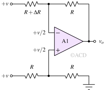
Resistor mismatches can re-introduce common mode gain into a difference amplifier even if the opamp's common mode rejection ratio is infinite. Let's understand this using a simple example, as shown in Figure 2.

In above figure, the amplifier's two inputs are excited using the common mode signal "+v". We have introduced a small resistance mismatch ΔR in the top \left resistor.
The voltage swing at the non-inverting terminal is "+v/2". Due to virtual short, the voltage at the inverting terminal is also "+v/2". Now applying KCL at the inverting terminal :
$$\cfrac{v/2-v}{R+\Delta{}R}+\cfrac{v/2-v_o}{R}=0$$
$$v_o=\cfrac{v}{2}\left(\cfrac{1}{1+\cfrac{\Delta{}R}{R}}+1\right)-\cfrac{v}{1+\cfrac{\Delta{}R}{R}}$$
Using binomial expansion, we get,
$$v_o\simeq{}\cfrac{v}{2}\cfrac{\Delta{}R}{R}$$
The above expression shows that output is proportional to the common mode signal "+v" and the mismatch in resistance. If the mismatch is zero, the output is zero with any common mode input. However, with any mismatch, there is a common mode gain. The gain is equal to ΔR/2R.
$$A_{cm}=\cfrac{v_o}{v}=\cfrac{\Delta{}R}{2R}$$
So, for 0.1% tolerance resistors, the mismatch could be 0.1%. This means ΔR/R = 0.1%. Therefore, the common mode gain (Acm) is :
$$A_{cm}(\text{dB})=20\log_{10}{(0.001/2)}=-66\,\text{dB}$$
Acm should have been -∞ dB (or 0 V/V) ideally, but it is -66dB (0.0005 V/V) due to 0.1% mismatch in resistance.
Frequently asked questions (FAQs)
Some frequently asked questions are listed below:
What is the difference between a difference amplifier and a differential amplifier?
The phrase "difference amplifier" can describe a specific type of differential amplifier that maintains a gain of 1. So, a difference amplifier is also termed as a unity gain differential amplifier. Both a differential amplifier and a difference amplifier produce an output directly proportional to the difference between inputs. Consequently, these terms are frequently employed interchangeably.
What is the difference between a difference amplifier and an instrumentation amplifier?
Difference amplifiers and instrumentation amplifiers belong to the category of differential amplifier circuits. An instrumentation amplifier, specifically, features input buffer amplifiers making the input impedance very high. The amplification level can be easily adjusted by altering a single resistor (RG). Furthermore, instrumentation amplifiers are offered as integrated circuits (ICs) that offer exceptionally high Common-Mode Rejection Ratio (CMRR).
Difference amplifier applications
Some very common applications of difference amplifier is mentioned below :
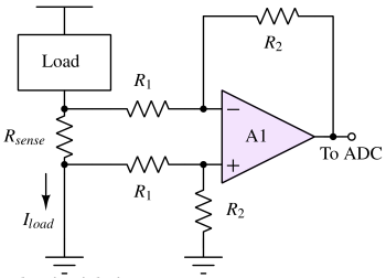
Current sensing
Current sensing is the process of determining the current through a load. Usually, the current is passed through a sense resistor (Rsense) as shown below. This generates a tiny voltage drop across the sense resistor. The voltage across the Rsense is detected and amplified using a difference amplifier.

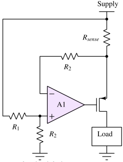
Inrush current protection

The current going to the load is passed through the sense resistor Rsense. The voltage drop is sensed using a difference amplifier whose output controls a MOSFET switch.
When the voltage drop across Rsense exceeds some threshold, the output of the difference amplifier goes high, and the switch is turned off. If the current is low enough, the output of the difference amplifier is low, and the MOSFET is fully turned on.
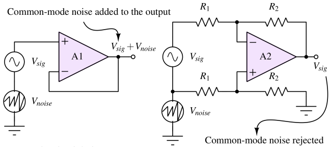
Common mode noise rejection

Common mode noise rejection refers to the ability of a system or device to attenuate or eliminate noise that is present equally and in phase on both signal lines (or conductors) relative to a reference, usually ground. In case of difference amplifier, the signal voltage is applied between the two input terminals.
Construction of instrumentation amplifier
A difference amplifier is used to make an instrumentation amplifier. A difference amplifier's input impedance is not infinite, which means it will draw current from the source voltage. An instrumentation amplifier has infinite input impedance, not drawing any current from the input voltage source.