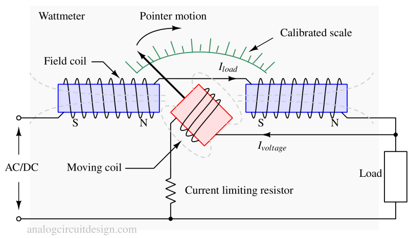
Wattmeter
A wattmeter is an electrical device used to measure the power consumed or supplied by an electrical circuit. It measures the rate at which electrical energy is being transferred, which is commonly referred to as power. The unit of power is the watt (W).
Wattmeters are commonly used in various applications, such as electrical testing, power monitoring, energy management, and industrial control systems. They are essential tools for understanding and managing power consumption in electrical systems.
Working principle of a Wattmeter
The principle of a wattmeter is based on the measurement of both current and voltage in an electrical circuit. It utilizes the relationship between these two variables to determine the power being consumed or supplied by the circuit.
Types of Wattmeter
- Electrodynamometer Wattmeter: Uses moving and fixed coils for AC power measurement, suitable for single-phase and three-phase circuits.
- Induction Wattmeter: Employs electromagnetic induction with a rotating disk for single-phase AC power measurement.
- Digital Wattmeter: Utilizes digital technology for AC and DC power measurement, often with advanced features.
Electrodynamometer Wattmeter

It works on the principle of torque induced on a current-carrying coil inside a magnetic field. It consists of a current and potential coil (Field and Moving coil, respectively). The current coil (Field coil) is connected in series with the load, allowing it to carry the current flowing through it. The potential coil is connected in parallel across the load or the circuit, allowing it to measure the voltage across the circuit.
The power measured by the wattmeter is the average power (True power/resistive power) :
$$P=V_{pc}\cdot{}I_{cc}\cdot{}cos{\left(phi{}\right)}$$
Vpc the voltage across the potential coil. Icc is the current across the current coil. φ is the angle between voltage and current. For pure resistive load, φ is zero.
When current flows through the current coil, it creates a magnetic field (proportional to the current) that exerts a force on the disc, causing it to rotate. Similarly, when voltage is applied across the potential coil, it generates a magnetic field (proportional to the voltage) that exerts a force on the disc. The combined effect of these magnetic fields results in disc rotation.
The disc rotates in proportion to the product of the current and voltage, which is equal to the power in the circuit. The pointer attached to the disc moves along a calibrated scale, indicating the power consumption or supply.
The electrodynamometer type of Wattmeter has a uniform scale. High accuracy can be obtained if carefully designed.
Why electrodynamometer type wattmeter is suitable for both AC and DC measurements?
When the current flow through a dynamometer instrument reverses, the field and moving-coil flux reverse directions. The pointer deflection is unaffected. This makes the instrument suitable for application to AC measurements, as well as DC measurements.
Induction Wattmeter
It works on the principle of electromagnetic induction. Since induction occurs with AC voltages and currents only, this device can measure the power for AC circuits only. The accuracy is not as good as the electrodynamometer-based wattmeter.
An induction wattmeter consists of two laminated electromagnets, Shunt Magnet, and Series Magnet. The shunt magnet is connected across the load and carries a current proportional to the supply voltage. The shunt magnet's coil is highly inductive so that its current lags the supply voltage by 90°. The series magnet is connected to the supply and carries the load current. The coil of the series magnet is made non-inductive. A thin aluminum disc mounted on a spindle is placed between the two magnets to cut the flux of the two magnets.
The fluxes produced by the two magnets induce eddy currents in the aluminum disc by electromagnetic induction. Due to the interaction between the fluxes and eddy currents, a deflecting torque is produced on the disc, causing the disc to move, and hence, the pointer connected to the disc moves over the scale and shows the value of power.
Digital Wattmeter
The digital wattmeter measures the current and voltage on the circuit thousands of times per second and calculates the electrical power by multiplying the current and voltage with the help of the microprocessor inside. The power reading is shown in a digital screen. Microprocessor based wattmeter can provide voltage and current profile log over time. The same digital wattmeter can also be used as a energy meter.
Applications of Wattmeter
Wattmeters are commonly used in various applications, such as electrical testing, power monitoring, energy management, and industrial control systems. They are essential tools for understanding and managing power consumption in electrical systems.
Example problem
A wattmeter measures the AC power delivered to a load as 200 W, and an ammeter and voltmeter indicate that the load current and voltage are 2.5 A and 100 V, respectively. Calculate the phase angle between the current and voltage.
Solution : True power = (VIcos{\left(phi{}\right)}), Apparent power = (VI)
Phase angle((phi{})) = (cos{}^{-1}\left(\cfrac{\text{True power}}{\text{Apparent power}}\right))
Wattmeter gives True power because it considers the angle between voltage and current. The Field coils, and Moving coil reacts according to the angle. So, 200W is True power (resistive power). Apparent power is the power that is perceived by independently measuring voltage and current. In this case, the apparent power is 250W.
Phase angle((phi{})) = (cos{}^{-1}\left(\cfrac{200}{250}\right)) = (36.86^o)
References
Some more details - How to Measure Electrical Power