Ammeter
An ammeter is a measuring instrument used to measure electric current. It is designed to be connected in series with the circuit or component through which the current is measured. The ammeter provides a low resistance path for the current to flow through, allowing it to measure its magnitude accurately.

Primary current sensing techniques
| Current sensing techniques | ||
|---|---|---|
| Invasive | Non-invasive | |
| Working principle | Require direct electrical contact with the circuit. The instrument is inserted in series with the circuit. | Does not require direct electrical contact. This method allows physical isolation from the circuit. |
| Advantages | Ultimate accuracy and simple design | No need to break the circuit, reduced power loss and Safety against high-voltage applications |
| Disadvantages | Unsafe for high voltage applications, Need isolation of sensitive components for measurement | Less accurate |
| Examples | PMMC, Moving iron ammeter, Electrodynamometer ammeter, Contact voltage probe etc | Current transformer, Rogowoski coil, Flux gate sensor, Hall effect sensor etc. |
Difference between Galvanometer and Ammeter
| Feature | Galvanometer | Ammeter |
|---|---|---|
| Definition | A device used to detect and measure small electric currents with the direction. | A device used to measure only the magnitude of electric current in a circuit. |
| Measurement Type | Measures small currents (usually in microamperes or milliamperes). | Measures larger currents (in amperes). |
| Construction | A coil carrying current is positioned within a magnetic field generated by a permanent magnet. The coil is connected to a needle, which moves along a scale to indicate both the magnitude and direction of the current. | Similar to a Galvanometer. Additionally, a shunt resistance (Rsh) is placed in parallel to Galvanometer to reduce the voltage drop while measuring high currents. This combined setup of Galvanometer + Shunt resistor is known as PMMC ammeter |
| Polarity Sensitivity | Polarity-sensitive (deflects in opposite directions for AC and DC). | Can measure both AC and DC with appropriate modifications. |
| Internal Resistance | High internal resistance, typically in the hundreds of ohms. | Low resistance, to minimize voltage drop. |
| Applications | Used in electrical experiments, bridge circuits, and detecting very small currents. | Used in electrical circuits, power systems, and industrial applications. |
Types of ammeter
Ammeters are classified based on the type of current they measure and their working principle :
flowchart TD
    A[Ammeter] --> B[Invasive]
    A[Ammeter] --> C[Non-Invasive]
    B[Invasive] --> D[DC]
    B[Invasive] --> E[AC & DC]
    C --> G[AC]
    C --> H[AC & DC]
    D --> I[PMMC / D'arsenvol]
    G --> J[Current transformer, Rogowski coil]
    E --> K[Contact voltage probe, Electrodynamometer, Moving iron vane]
    H --> L[Hall sensor, Anisotropic magneto resistance, flux-gate sensor]
Permanent Magnet Moving Coil (PMMC or d’Arsonval type)
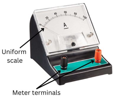
This is a kind of invasive technique where the circuit connection is broken to insert an ammeter. The ammeter is inserted in series to complete the circuit. To drop minimal voltage through the ammeter, the resistance offered by an ammeter should be very low.
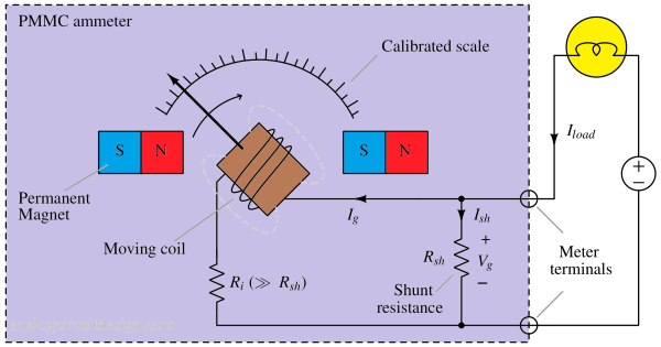
In Fig 1,
- Ri = Internal resistance of an ammeter/galvanometer.
- Rsh = Shunt resistance; this will carry the majority of the current.
- Vg = Voltage across the Rsh
- Ig = Galvanometer current
- Iload = Ish + Ig
The instrument will sense the voltage (because its own impedance is high, Ri). Let's derive the circuit current from know parameters. Unknown is Iload. We know Vg, Ri, Rsh. $$I_{sh}=\cfrac{V_g}{R_{sh}}$$ $$I_{load}=I_{sh}+I_g=\cfrac{V_g}{R_{sh}}+\cfrac{V_{g}}{R_i}$$

In Fig 2(a), A Galvanometer is used to create an Ammeter. A galvanometer is a device that detects presence of current. Fig 2(b) shows how an ammeter is used in a circuit to measure current. The ammeter is inserted in series to measure the current.
Amplified PMMC
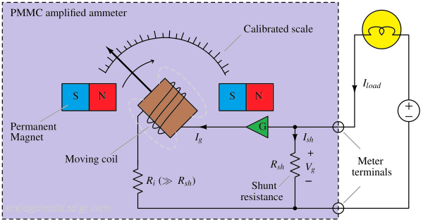
In an amplified ammeter (as shown in Fig 3), the sensitivity can be increased manifold if a precision amplifier (G) is added after the Shunt resistance. It would allow the use of very low Rsh that will help reduce the voltage drop and save significant power.
Moving Iron Type Ammeter
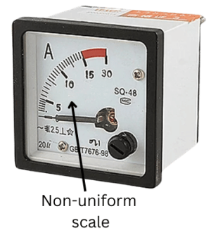
The moving iron vane meter is a simple type of measuring device that can be used for both AC and DC measurements. Unlike the d’Arsonval meter, which uses permanent magnets, it operates based on induced magnetism. Its working principle relies on the repulsion between two concentric iron vanes—one stationary and one movable—positioned within a solenoid. The movable vane is connected to a pointer, which displays the measurement.
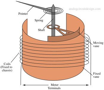
Working principle of moving iron ammeter
When current passes through the fixed coil, the two iron vanes become magnetized, with their upper ends acquiring north poles and their lower ends acquiring south poles for a given current direction. Since like poles repel each other, the resulting unbalanced force, acting tangentially on the movable element, causes it to rotate against the opposing force of the springs.
Electrodynamometer ammeter
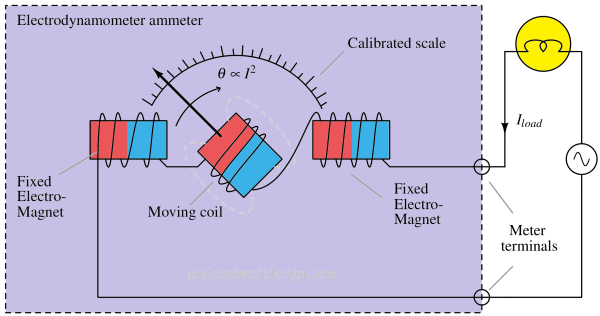
The electrodynamometer is capable of measuring both alternating and direct voltage and current. It functions similarly to a permanent magnet moving coil meter, but instead of a permanent magnet, it utilizes an electromagnet. The magnetic field in the electrodynamometer is generated by the same current that passes through the moving coil.
Rectifier ammeter
A rectifier ammeter is a modified PMMC ammeter used to measure alternating current (AC). PMMC ammeters are capable of measuring only DC current not AC current. A bridge rectifier is added into a PMMC instrument to convert AC into DC. It is also an invasive measurement method. The waveform of the current and voltage affects the accuracy of the rectifier instrument. The rectifier has some capacitance which affects the maximum operating frequency for AC measurements.
Comparison of different analog invasive ammeters
| Properties | PMMC | Moving Iron Ammeter (Iron vane) |
|---|---|---|
| Reading scale | The moving coil instrument has a uniform reading scale because deflection is directly proportional to current. | The moving coil instrument has a non-uniform scale because deflection of pointer is proportional to square of current. |
| Measurement | Moving coil instruments can measure direct current (DC) only. | Moving iron instruments can measure direct current (DC) as well as alternating current (AC). |
| Magnet | Moving coil instrument uses permanent magnet. | Moving iron instrument uses electromagnet. |
| Accuracy | Moving coil instruments are comparatively more accurate. | Moving iron instruments are less accurate than moving coil instruments. |
| Robustness | Moving coil instruments are very sensitive in construction, i.e. these are less robust. | Moving iron instruments are robust in construction. |
| Controlling torque | Moving coil instruments use a control spring to provide the controlling torque. | In moving iron instruments, the controlling torque is provided by either gravity control or spring control. |
| Sensitivity | Moving coil instruments are more sensitive. | The sensitivity of moving iron instrument is less. |
| Rotating element | In a moving coil instrument, the rotating element is a coil of fine wire. | Moving iron instrument has a core of soft iron as a rotating element. |
| Range of measurement | The basic current range for a moving coil instrument is 10 μA to 100 mA. | The range of current for a moving iron instrument is relatively high because of non-uniform scale, from 10 mA to 100 A. |
| Power consumption | Moving coil instruments consumes less power because magnetic field is generated by permanent magnets. | Moving iron instruments consumes high power due to losses in electromagnet. |
| Hysteresis loss | The hysteresis loss does not occur in a moving coil instrument. | The hysteresis loss takes place in a moving iron instrument. |
| Cost | Moving coil instruments are expensive. | Moving iron instruments are relatively less expensive. |
Picoammeter
To measure current in the picoampere range, methods like voltage integration is used. The small current is used to slowly charge or discharge the voltage across a known capacitor using opamp. The voltage rise or fall linearly with time. The current can be determined using following formula.
$$i=C\cfrac{V_1-V_2}{T_1-T_2}$$
Digital ammeter
Unlike analog ammeters, which use a mechanical pointer and a calibrated scale, digital ammeters display the current readings as numerical values on a digital screen. They are based on microcontrollers/ASICs.
Working principle of Digital Ammeters
The working principle of a digital ammeter involves using current sensing mechanisms, such as Hall effect sensors or Shunt resistors. The Hall effect sensor detects the magnetic field generated by the current flowing through a conductor and converts it into a proportional electrical signal. The shunt resistance creates a voltage drop across it, amplified to a usable voltage. The generated signal is then processed by electronic circuitry, including analog-to-digital converters (ADCs), to convert the analog signal into digital data.
The digital data is then displayed on a digital screen, which may be an LCD (liquid crystal display), LED (light-emitting diode), or other types of digital display. The digital readout typically shows the current value directly in amperes (A) or milliamperes (mA), depending on the range of the ammeter.
Advantages of Digital Ammeters
Digital ammeters offer several advantages over analog ammeters, including:
- High accuracy: Digital technology provides greater precision and reduces the chances of reading errors due to parallax or misinterpretation of analog scales.
- Multiple ranges: Digital ammeters often have multiple ranges, allowing them to measure a wide range of currents and automatically switch between the appropriate range based on the current being measured.
- Enhanced features: Some digital ammeters may have additional features like data logging, peak current capture, min/max current readings, and communication ports for data transfer.
- Compact and easy to read: Digital displays are typically more compact and easier to read, especially in low-light conditions.
- Reduced loading effect: Digital ammeters usually have higher input impedance than analog ones, causing less disruption to the measured circuit.
Digital clamp meters
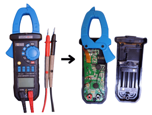
A clamp meter (also called a clamp ammeter) is a non-invasive current measuring device that allows electricians and engineers to measure current without breaking the circuit. It works by detecting the magnetic field generated by the flowing current.
Working principle of a clamp meter
The clamp meter has current-sensing jaws that detect the magnetic field around a conductor. Using electromagnetic induction (for AC) or the Hall effect sensor (for DC), it converts the magnetic field into an electrical signal. The signal is processed and displayed as a current reading on the digital or analog screen.
Advantages
- Non-contact measurement (no need to break the circuit).
- Safe for high-voltage and high-current systems because it is galvanically isolated.
- Portable and easy to use.
- Reasonable accuracy and precision.