Galvanic Isolation
Galvanic isolation means isolation of two electrical circuits with no direct current (DC) path between them. There could be magnetic, capacitive, or optical path between them. There is no physical conductor connection running between the two isolated electrical systems. In other words, the energy transfers via field rather than electrical connections.
This allows the two isolated electrical systems to possess different ground potentials. Also, it allows the operating voltage to be different in two parts of the system while carrying the same signal. The signal levels get superimposed over local DC voltages and system requirements are met. In high-voltage systems, freely flowing DC current into low-voltage systems through high-voltage subsystems can be dangerous.
Ground Loop
In an electrical system, a ground loop is circuit path appears when two circuits share the same ground line and also have DC path between them. These ground paths can function as large loop antennas, picking up environmental noise and inducing currents within the grounding system. A common source of noise picked up by ground loops is the 50 Hz or 60 Hz magnetic field generated by AC power.
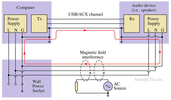
Ground loops are commonly noticeable in audio equipment, often causing unwanted humming or buzzing sounds that can interfere with the clarity of your audio signal.
How Galvanic Isolation prevents ground loop formation?
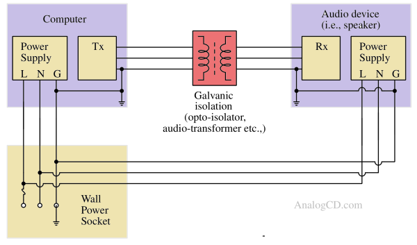
Optical or galvanic isolation devices enable signal connections without the inclusion of a common ground connection. With this isolation, the current cannot pass through the isolated ground potential if the potential of one ground is raised.
Common Galvanic Isolation methods
Some methods to achieve galvanic isolation are listed below :
Transformer
The most common form of galvanic isolation is the transformer. The exchange of energy in a transformer happens by changing magnetic flux. There is no physical wired connection between the primary and secondary windings of the transformer. This allows the primary and secondary windings to have different ground potentials.
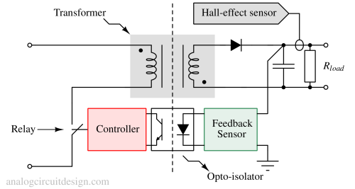
Multi-output transformer (transformers having multiple secondary windings) allows independent loads having different ground potentials.
Hall effect sensors
A Hall effect Sensor senses the magnetic field information non-invasively and does not require direct wired contact with the system. The magnetic field induces an electric field across a conductor and produces a current. Since a field induces the electric field, not a wired connection, the galvanic isolation is maintained.
Relays
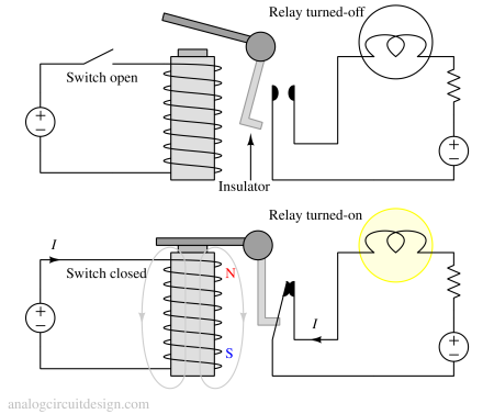
Relays are a very common way to achieve galvanic isolation. The key to galvanic isolation in relays is that the coil and the contacts are physically separated inside the relay, often with an air gap or insulating material. This means that even though the coil side and contact side are within the same relay housing, there is no direct electrical connection between them.
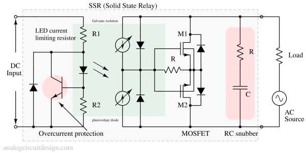
Solid-state relays (SSRs) also provide galvanic isolation in a similar manner to traditional electromechanical relays, but these devices achieve this isolation using optoisolators instead of mechanical parts (solenoids) as shown in Fig 3.
Opto-isolator or optical isolation
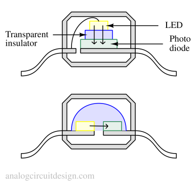
An optoisolator provides galvanic isolation between two parts of an electrical circuit using light as a medium. It comprises an input LED (light-emitting diode) and an output phototransistor or photodiode. When current flows through the LED, it emits light, activating the phototransistor or photodiode on the output side. The output circuit remains electrically isolated from the input circuit because there is no direct electrical connection between them.
Why is galvanic isolation required ? Applications
- Galvanic isolation is also used for safety, preventing accidental electric shocks.
- The hall effect sensor method is used for non-invasive current sensing (AC and DC).
- Protecting expensive processors, ASIC, or FPGAs from the risk of damage in a high voltage system.
- Breaking ground loop in circuits of motor drives or power converter systems.