Proportional Integral Derivative (PID) control
PID stands for Proportional Integral Derivative Controller. By fine-tuning the weights of these three components (Kp, Ki, Kd), a PID controller can effectively control a wide range of systems, from simple temperature regulation in ovens to complex industrial processes in manufacturing and automation. The goal is to maintain the process variable as close to the setpoint as possible while minimizing overshoot and oscillations with optimum response time.
In the mid-1900s, various technological and analytical ideas converged to establish PID as a widely accepted and effective control method.
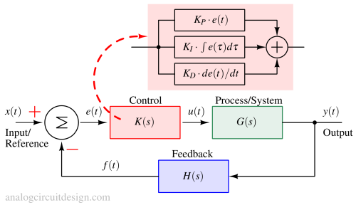
$$u(t)=K_pe(t)+K_i\int{}e(\tau{})d\tau{}+K_d\cfrac{de(t)}{dt}$$
$$K(s)=K_p+\cfrac{K_i}{s}+K_d\cdot{}s$$
PID controller theory with example
The working mechanism and theory of a PID controller are explained below:
Proportional
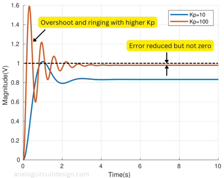
The "P" term is directly related to how big the present error (e(t)) is. For instance, if the error is large, the control output will be correspondingly large, thanks to the "Kp" gain factor. But if you only use proportional control, there will always be a some error left between the desired set point and the actual process value because the controller needs some non-zero error to produce a non-zero output. Additionally, the error decreases as "Kp" increases.

Let's take an example of a second-order process with unity feedback:
$$G(s)=\cfrac{1}{(s+1)(s+2)}$$
$$H(s)=1$$
$$K(s)=K_p$$
$$K_p=10$$
The output (using a closed-loop transfer function) can be written as:
$$y(s)=\cfrac{K_p}{s^2+3s+2+K_p}x(s)$$
Using the final value theorem for a unit-step response, the steady-state output can be found:
$$y(t\rightarrow{}\infty)=\cfrac{K_p}{2+K_p}$$
$$e(t\rightarrow{}\infty)=1-y(t\rightarrow{}\infty)=\cfrac{2}{2+K_p}$$
From above we observe that error is inversely proportional to Kp. At steady-state, output y(t) is 0.83V and error e(t) is 0.16V as mentioned in Fig 3.
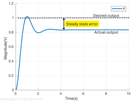
Increasing the Kp alone can decrease the steady-state error. However, it can cause excessive ringing and oscillation at the output which is undesirable.
Integral
The "I" term continuously adds up the error over time to create the integral part. Even if the steady-state error from the proportional part is tiny and non-zero, the integral part will keep accumulating and growing over time. This growing integral part compels the system to move in a direction that reduces the error. The integral part stops growing only when the error reaches zero. Now for a non-zero output, we have a zero error because the integral term has accumulated past non-zero error terms at the controller output.
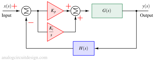
Moving with the same example as in proportional control, we add an integral term at the controller. Now it becomes proportional-integral control. G(s), H(s) and Kp remain same, K(s) changes to :
$$K(s)=K_p+\cfrac{K_i}{s}$$
$$K_i=6$$
The output and error can be written as:
$$y(s)=\cfrac{sK_p+K_i}{s^3+3s^2+(K_p+2)s+K_i}x(s)$$
$$e(s)=\cfrac{s(s+1)(s+2)}{s^3+3s^2+(K_p+2)s+K_i}x(s)$$
Using the Final value theorem (to find steady-state values), y(t) = 1V and e(t) = 0V.
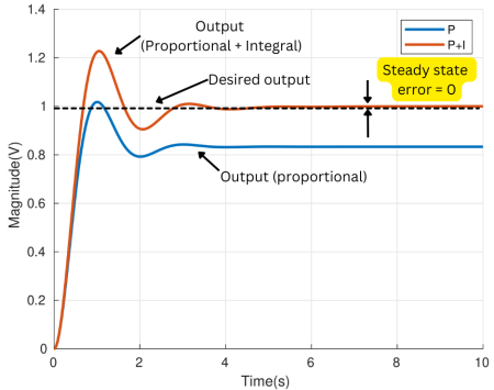
As shown in the above figure, adding an integral term with the proportional controller, the steady-state error is reduced to zero. However, the overshoot is still there. This type of controller is called proportional-integral (PI) controller.
Derivative
The "D" term offers prediction of how the error will change in the future, based on its current rate of change. It's like anticipating and acting proactively. When the error changes rapidly, the "D" term has a stronger control or damping effect.
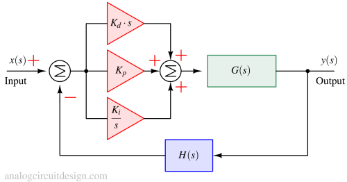
Adding to the previous example as in proportional-integral control, we add a derivative term at the controller. Now it becomes Proportional-Integral-Derivative control. G(s), H(s), Kp and Ki remain same, K(s) changes to :
$$K(s)=K_p+\cfrac{K_i}{s}+K_d\cdot{}s$$
$$K_d=2$$
The output and error can be written as:
$$y(s)=\cfrac{s^2K_d+sK_p+K_i}{s^3+(3+K_d)s^2+(K_p+2)s+K_i}x(s)$$
$$e(s)=\cfrac{s(s+1)(s+2)}{s^3+(3+K_d)s^2+(K_p+2)s+K_i}x(s)$$
Using the Final value theorem (to find steady-state values), y(t) = 1V and e(t) = 0V. Same as the Proportional-Integral controller. However, if we see the graph in the following figure, the overshoot is much less.
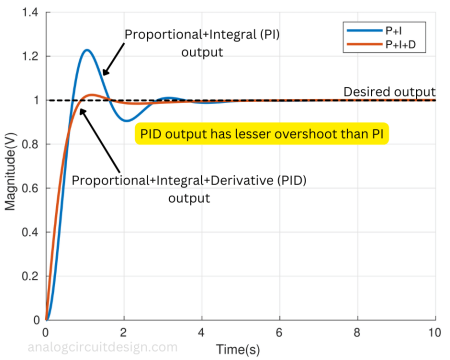
A derivative controller alone may not add value to the system because the derivative controller reacts only to a change. So, at a steady state, the output of a derivative controller will be zero. However, it adds a lot of value in the presence of Proportional-Integral control.
Example of Proportional-Integral controller with MATLAB modeling
$$K_p=10$$
$$K_i=6$$
$$G(s)=\cfrac{1}{(s+1)(s+2)}$$
$$H(s)=1$$
Matlab code to model a simple proportional-integral controller
KP=10;
KI=6;
num=1;
den=[1 3 2];
Gs=tf(num,den);
Ks=tf(KP)+tf(KI,[1 0]);
Hs=tf(1);
cl_sys=Ks*Gs/(1+Hs*Ks*Gs);
step(cl_sys);`
Example of Proportional-Integral-Derivative controller with MATLAB modeling
$$K_p=10$$
$$K_i=6$$
$$K_d=2$$
$$G(s)=\cfrac{1}{(s+1)(s+2)}$$
$$H(s)=1$$
Matlab code to model a simple proportional-integral-derivative controller
KP=10;
KI=6;
KD=2;
num=1;
den=[1 3 2];
Gs=tf(num,den);
Ks=tf(KP)+tf(KI,[1 0])+tf([KD 0],1);
Hs=tf(1);
cl_sys=Ks*Gs/(1+Hs*Ks*Gs);
step(cl_sys);
Tuning of PID controller
Tuning a PID controller means finding the right settings for its parts (Kp, Ki, and Kd) to make a control system work well. There are different ways to do this, but two common methods are "Trial and error" and the Ziegler-Nichols method.
Trial and error method
In the "Trial and error" method, we start by setting Ki and Kd to zero. Then, we increase Kp until the system starts to oscillate a bit. More Kp makes the system faster, but we have to be careful not to make it unstable. After setting Kp for a faster response, we need to raise Ki to stop the oscillations and reduce errors. However, too much Ki can cause more overshoot. A bit of overshoot is okay for a fast system. Finally, we add Kd to make the system react quickly to its target. Kd reduces overshoot but can make the system sensitive to noise. Engineers often need to balance these factors to meet their needs.
Ziegler-Nichols method
The Ziegler-Nichols method is similar. We begin by setting Ki and Kd to zero and raising Kp until the system starts to oscillate. Then, we note the critical gain (Kpc) and the oscillation frequency (fc). Using these values, you adjust Kp, Ki, and Kd as shown in a table:
| Control | Kp | Ki | Kd |
|---|---|---|---|
| P | 0.5Kpc | ||
| PI | 0.45Kpc | 1.2fc | |
| PID | 0.6Kpc | 2fc | 1/(8fc) |