H-bridge circuit
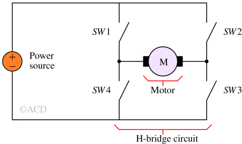
An H-bridge circuit forms the fundamental configuration for controlling a DC motor's direction—either clockwise or counterclockwise. Comprising four switches (made using relays or transistors) arranged in the shape of the letter 'H,' this setup allows the motor to move in different directions. Engaging one pair of diagonally opposite switches propels the motor in a particular direction (clockwise) while activating the opposite pair drives the motor in the opposite direction (counterclockwise). To regulate the motor's speed, a pulse width modulated signal is employed. Additionally, freewheeling diodes are integrated to safeguard the MOSFETs against potential damage from fly-back voltages that may occur if the motor abruptly stops.

Modern H-bridge configurations not only reverse the motors' direction but also supply the essential current for driving them. They serve as an intermediary between low-power microcontrollers (such as Arduino) and motors that require substantial power, acting as a buffer to manage this power discrepancy. That is why they are also termed Motor drivers.
H-Bridge Working
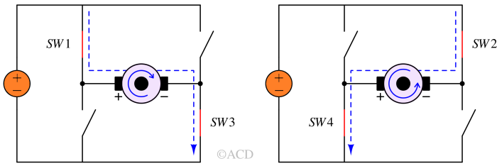
A DC motor's direction of rotation is determined by the polarity of its connections. By closing switches SW1 and SW3, the positive terminal connects to the motor's left side while the negative terminal connects to the other side. This configuration initiates the motor's rotation in one direction.

By closing switches SW2 and SW4, the positive terminal is linked to the motor's right side while the negative terminal connects to the left side. This setup prompts the motor to rotate in the opposite direction.
Construction of H-bridge circuit
An H-bridge can be constructed using four transistors. The article about transistors reveals that transistors can function as switches, controlled by altering the voltage on the base (in BJTs) and gate (in MOSFETs). Leveraging this switch-like characteristic allows manipulation of the motor's direction by activating and deactivating the four transistors in the provided circuit. Typically, these transistors are managed by a microcontroller, like Arduino, facilitating precise control over the motor's movements in either direction.
Specifications of the transistor for H-bridge circuit
- Does not heat up when supplying high-current.
- The collector-emitter voltage in BJT and Drain-source voltage in FETs should be very small when the transistor is turned on.
- The breakdown voltage of the transistors should be higher than the motor's applied voltage.
Protection diodes
These diodes are also called free-wheeling diodes. The motors have coils in them which behave as inductors. When the supply to those inductors is turned off to stop the motor or reverse the direction of the motor, the current still flows in the same direction for a while. The current is trying to flow through the off-state switch (a very high resistance path). This leads to very high voltage spikes across the transistors which can be higher than the breakdown voltage of the transistors. Going above or near the breakdown voltage can destroy the transistors. A diode can be placed in parallel to the transistor to limit the voltage rise which can act as a clamp.
Decoupling capacitor
A decoupling capacitor can source excess current when the supply is turned off. This prevents the supply line from going down and resetting the microcontroller.
H-bridge motor driver
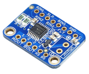
The limitations of microcontroller pins, with an output capability of a few mA, prevent direct powering of heavy loads like motors. To control large currents required by a DC motor, a dedicated circuit is essential. A simple MOSFET circuit permits on/off control or variable speed via pulse-width modulation (PWM). However, for more comprehensive motor control including directional changes, an H-bridge circuit is preferable. H-bridges employ four transistors to manage both motor rotation and speed. Integrated Circuits (ICs) such as L293D, L298N, and DRV8833 offer a convenient and compact solution by integrating multiple transistors into a single package with the necessary protection included. Some ICs provide dual H-bridge circuits, enabling support for a pair of motors, ideal for robotics applications.

Applications of H-bridge circuits
Applications of H-bridge circuits :
- Motor driver
- DC-to-AC converters (power inverters)
- AC-to-AC converters