Power MOSFET
A power MOSFET (Metal-Oxide-Semiconductor Field-Effect Transistor) is a type of MOSFET designed to handle high power and voltage levels. MOSFETs are three-terminal devices that control the current flow through a channel between the source and drain terminals based on the voltage applied to the gate terminal.
Power MOSFETs are used in various applications that require high-power handling, such as power supplies, motor control, inverters, and switching applications. They offer advantages like high efficiency, fast switching speed, low on-resistance, and high power density.
Construction of Power MOSFET
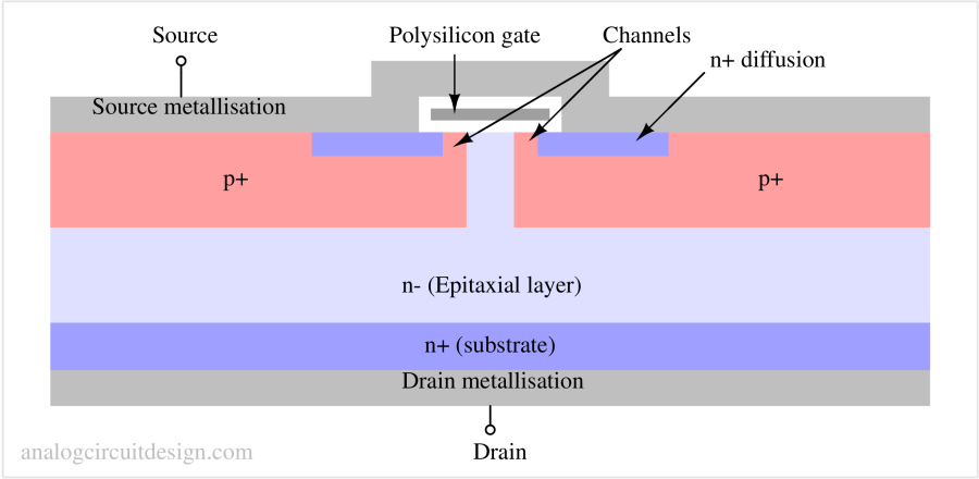
Parasitic components in the construction of power MOSFET
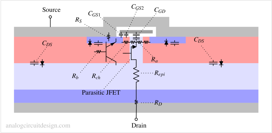
The source and body (bulk) are tied together. Therefore CDS is equivalent to CDB.
RS : It represents the resistance offered by the metallization and n+ contact region in the source terminal.
RJFET : It is the resistance offered by the parasitic JFET transistor. Usually, the VGS of this parasitic JFET is large, so the resistance is very low, but still important to count when very resistance is required. To learn more about JFET, visit this page: JFET
Repi : It represents the resistance of the epitaxial layer. The resistance of the epitaxial layer is a function of the voltage rating of the device, as high-voltage MOSFETs require a thicker epitaxial layer.
RD : Similar to Rs, it represents the resistance offered by the metallization and n+ contact region in the source terminal.
Operating principle of Power MOSFET
Similar to low-power ordinary MOSFETs, power MOSFETs control the flow of current between the two terminals (source & drain) by changing the voltage on the gate terminal. A channel is formed between the source and drain when a positive voltage is applied to an enhancement type NMOS's gate terminal which allows the flow of current.
By increasing the VGS(gate-source) voltage, the drain current will increase. To learn more about normal MOSFET and its I-V characteristics, visit this page: MOSFET
Simplified model of power MOSFET
DC model
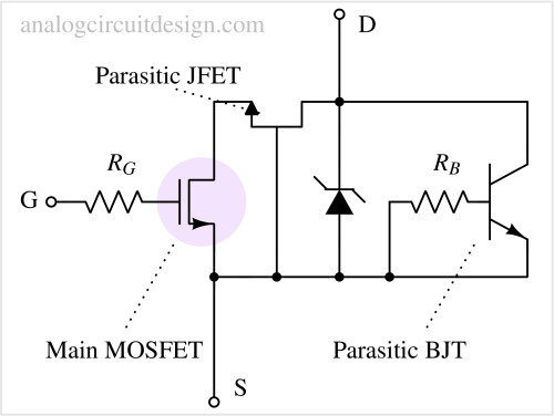
Switching model
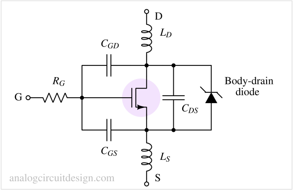
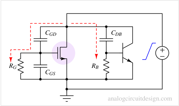
dVDS/dt turn-on model
Key specifications of Power MOSFET
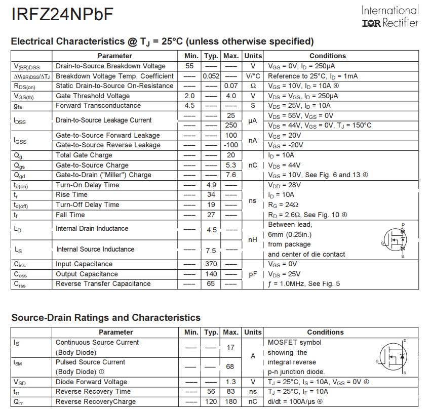
When selecting a power MOSFET for a specific application, factors like voltage and current requirements, switching frequency, thermal considerations, and overall system design must be considered. Manufacturers provide detailed datasheets containing relevant specifications and performance characteristics to assist in selecting.
Voltage rating
Power MOSFETs are designed to handle high voltage levels, typically ranging from a few tens to several hundred volts.
Drain-Source junction: Exceeding the maximum operating voltage in the drain-source junction can trigger avalanche breakdown causing the device to conduct unintentional and uncontrolled current, potentially damaging it and other circuit elements due to excessive power dissipation.
Gate-Bulk/source/drain breakdown voltage: The gate oxide is very thin so for a very small applied voltage, the electric field may reach the breakdown levels. In the datasheets, manufacturers often state a maximum gate-to-source voltage (depending on the thickness of gate oxide), and exceeding this limit can result in the destruction of the transistor. Furthermore, a high gate-to-source voltage significantly reduces the lifetime of the MOSFET by degrading the drain current magnitude.
Current rating
They can handle significant current levels ranging from a few amperes to hundreds. The current is limited by heating due to the self-heating of the junction, resistive losses in internal components such as bond wires, and electromigration in the metal interconnects.
On-state resistance
Power MOSFETs have low on-resistance (Rds(on)), which reduces power losses and increases efficiency.
Switching speed
They have fast switching characteristics, allowing rapid on/off transitions. The switching speed of the MOSFET is determined by how quickly the voltages can be changed across the parasitic capacitors (CGD, CGS, CDS).
Parasitic capacitances
There are three parasitic capacitances associated with Power MOSFET. Two of these capacitors, the CGS and CGD capacitors, correspond to the actual geometry of the device. In contrast, the CDS capacitor is the capacitance of the base-collector diode of the parasitic bipolar transistor (body diode). These parasitic capacitors' values are indirectly given by CISS, CRSS, and COSS in the manufacturer's datasheet.
CGS - The gate electrode's source and channel region overlap form the CGS capacitor. The actual geometry of the regions defines the value and stays constant (linear) under different operating conditions.
$$C_{GS}=C_{ISS}-C_{RSS}$$
CGD - The CGD capacitor is the result of two effects. Part of it is the overlap of the JFET region and the gate electrode in addition to the capacitance of the depletion region, which is non-linear. This capacitor provides an undesirable feedback path from input to output which causes overshoot and ringing at the output. The equivalent CGD capacitance is a function of the drain-source voltage of the device approximated by :
$$C_{GD}=\cfrac{C_{GD0}}{1+K_1\sqrt{V_{DS}}}$$
$$C_{GD0}=C_{RSS}$$
CDS - The CDS capacitor is also non-linear since it is the junction capacitance of the body diode. Its voltage dependence can be described as shown below :
$$C_{DS}=\cfrac{C_{DS0}}{K_2\sqrt{V_{DS}}}$$
$$C_{DS0}=C_{OSS}-C_{RSS}$$
Gate drive requirements
Power MOSFETs generally require a higher gate drive voltage than their low-power counterparts to ensure proper turn-on and turn-off.
Heat dissipation
Due to the high power handling capability, power MOSFETs generate heat during operation. Adequate heat sinking or cooling mechanisms are necessary to ensure proper thermal management.
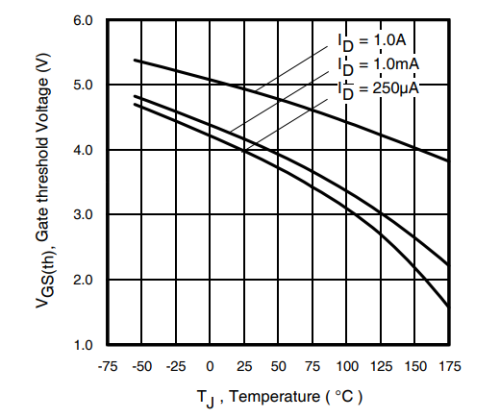
Threshold voltage
Applications of Power MOSFET
Power Supplies: Power MOSFETs are used in linear and switching power supplies to regulate voltage and efficiently convert power. They enable high-frequency switching, reducing power losses and increasing overall efficiency.
Motor Control: Power MOSFETs play a crucial role in motor control applications, such as variable speed drives, robotics, electric vehicles, and industrial automation. They precisely control motor speed and direction by switching the current to the motor windings.
Switched-Mode Power Conversion: Power MOSFETs are integral components in various switched-mode power conversion circuits, including DC-DC converters, AC-DC converters, and inverters. They enable efficient conversion and regulation of electrical power in applications like renewable energy systems, telecommunications, and consumer electronics.
Class-D Audio Amplifiers: Power MOSFETs are widely used in Class-D audio amplifiers due to their high efficiency and fast switching characteristics. Class-D amplifiers are known for their energy efficiency, making them suitable for battery-powered devices, audio systems, and car audio applications.
Lighting Systems: Power MOSFETs are employed in LED lighting systems, which are used for driving and controlling LED arrays. They enable efficient switching of current to illuminate LEDs and allow dimming functionality.
Uninterruptible Power Supplies (UPS): Power MOSFETs are utilized in UPS systems to provide backup power during main power outages. They enable efficient power conversion and switching between AC mains and battery power.
Renewable Energy Systems: Power MOSFETs are used in solar inverters and wind turbine systems to convert and regulate DC power generated from renewable energy sources into usable AC power for the grid or local consumption.
Electric Vehicle (EV) Powertrain: Power MOSFETs are employed in EV powertrain systems, including motor controllers, battery management systems, and onboard chargers. They provide efficient power switching and control for the high-voltage methods used in electric vehicles.
Form factor or Packages available for Power MOSFETs
Power MOSFETs are available in various packages, such as TO-220, TO-247, D2PAK, and DFN, to suit different application requirements. They may also include features like built-in protection circuits (over-current or over-temperature protection) and advanced gate drive technologies.